





Choosing High-Voltage Transformers for Utility-Scale Solar Power Plants
Choosing High-Voltage Transformers for Utility-Scale Solar Power Plants
Selecting a high voltage transformer for solar power plants is not a routine equipment purchase. It is a decision that affects grid connection, plant availability, energy losses, maintenance access, and the project’s ability to meet operating obligations for decades. For a utility-scale photovoltaic project, the transformer sits at the point where DC generation becomes a grid-facing asset. If its voltage configuration, impedance, insulation system, or protection philosophy is poorly matched to the plant, the consequences can extend far beyond a replacement cost.
Project teams often begin with capacity and voltage, which is reasonable, but incomplete. Two transformers with the same MVA rating can behave very differently when exposed to inverter harmonics, high ambient temperatures, dusty sites, frequent reactive-power commands, or a weak utility grid. The better approach is to define the electrical duty first, then evaluate the transformer design, accessories, testing scope, delivery plan, and service support against that duty.
Start with the Solar Plant’s Actual Electrical Architecture
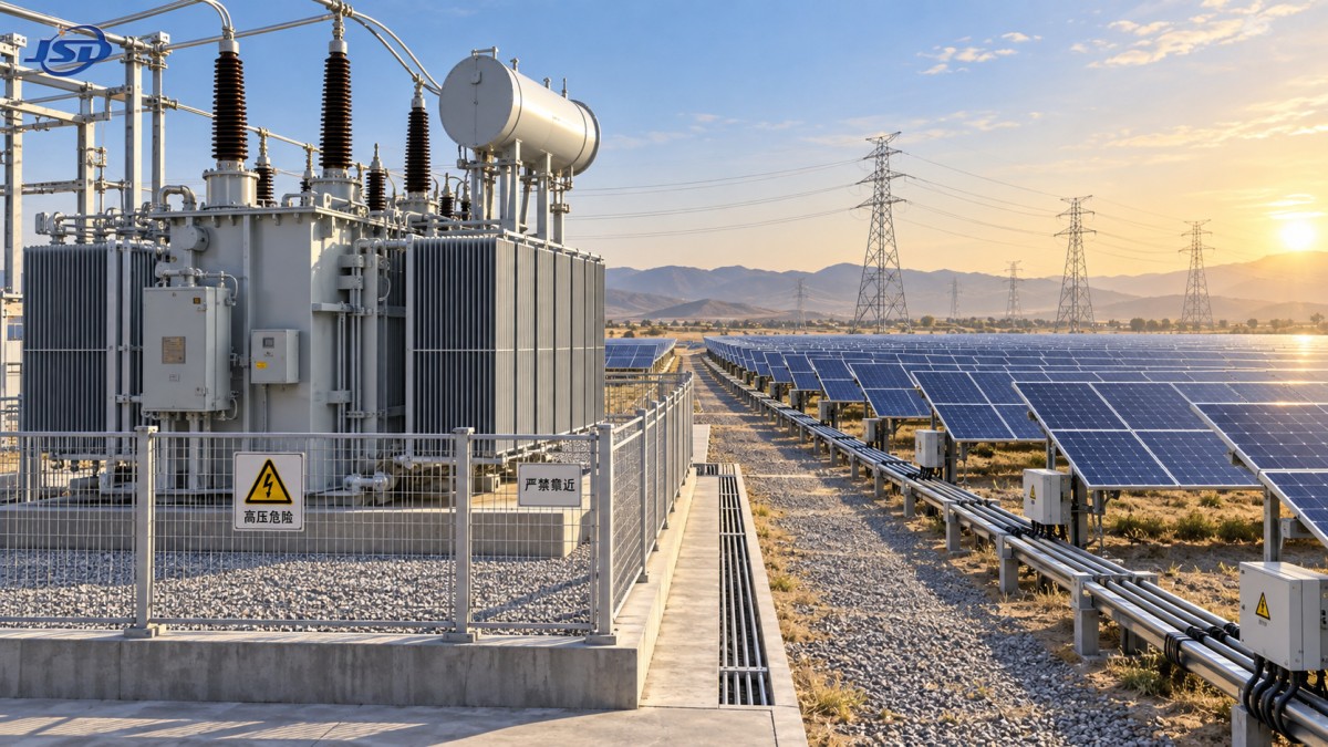
A utility-scale solar facility usually has several transformation stages. Inverter stations raise low-voltage AC to the medium-voltage collector level, while a main step-up transformer raises collector voltage to the transmission or sub-transmission voltage required by the grid operator. In some projects, a pad-mounted unit combines practical distribution functions in a compact outdoor arrangement. These roles should not be evaluated as though they carry the same operating stress.
Before requesting quotations, the project team should freeze, or at least clearly state, the following information: inverter output voltage, collector-system voltage, point-of-interconnection voltage, expected export capacity, reactive power requirement, grounding arrangement, grid fault level, and utility protection requirements. A transformer supplier can only make sound design recommendations when these interfaces are known. Leaving them open until late in procurement is one of the easiest ways to create expensive redesign work.
The grid connection voltage is particularly important. A plant connecting at 34.5 kV has very different insulation, bushing, clearance, and switching considerations from one connecting at 69 kV, 115 kV, or higher. The same is true for winding arrangement. Delta and grounded-wye configurations influence fault-current behavior, zero-sequence paths, harmonic circulation, and relay settings. The preferred vector group should be coordinated with the collector network and the utility’s grounding philosophy rather than copied from an earlier project.
Capacity Is More Than the Plant’s MW Nameplate
A common mistake is sizing the transformer strictly from the plant’s AC nameplate. In practice, the transformer must also accommodate power-factor operation, reactive power obligations, possible DC/AC oversizing, auxiliary loads, ambient temperature, and the owner’s expected operating margin. A plant may rarely deliver its theoretical peak output, but that is not a sufficient basis for undersizing. Grid-support functions can increase current demand even when active power is constrained.
The right question is not simply, “What is the transformer’s rated capacity?” It is, “What loading profile will it see during its hottest, most electrically demanding operating conditions?” For oil-filled equipment, loading capability is tied to winding hot-spot temperature, top-oil temperature, cooling mode, and insulation aging. A transformer that looks adequate in a mild climate may run with far less thermal headroom at a high-temperature desert site.
It is also worth checking whether the proposed rating assumes natural cooling only or includes forced-air stages. Forced cooling can be appropriate, but it adds fans, control circuits, alarms, maintenance needs, and failure modes. If a unit depends on fans to meet contractual output during peak conditions, the redundancy of those fans and the behavior following a fan failure should be documented clearly.
Loss Evaluation Should Reflect Operating Reality
Transformer losses are often evaluated only through an initial-cost comparison. That can lead to the cheapest unit winning even where its lifetime energy cost is materially higher. No-load loss is present whenever the transformer is energized, including overnight periods. Load loss varies with current and therefore follows plant production more closely. Both matter, but their financial weight depends on how the solar plant is dispatched, curtailed, financed, and metered.
For an export transformer that remains energized continuously, low no-load loss deserves close attention. For inverter-duty transformers with significant daily load variation, load-loss performance and thermal behavior may be more influential. The bid evaluation should ask suppliers to state losses at the specified temperature and reference standard, then apply one consistent economic-loss methodology across all bidders. Comparing values provided under different assumptions produces a false sense of precision.
Efficiency claims also need context. A quoted efficiency figure may be technically accurate at a particular loading point, yet not describe annual operating performance. Project managers should request guaranteed loss values, test requirements, permitted tolerances, and the commercial remedy if guaranteed values are exceeded. That is more useful than treating a single headline percentage as the complete selection criterion.
Inverter Harmonics and Voltage Distortion Cannot Be Treated as an Afterthought
Solar inverters are highly controlled devices, but their switching behavior and the wider collector system can still introduce harmonic currents and voltage distortion. Cable capacitance, filter arrangements, resonance conditions, and changing inverter operating modes can affect the transformer in ways that a conventional utility load may not. The issue is not that every solar transformer needs an exotic design; it is that the manufacturer needs enough system information to assess the duty correctly.
At minimum, share inverter data, expected harmonic spectrum where available, number of inverter blocks, collector cable details, and any harmonic-study findings. Harmonic current can increase eddy-current loss and localized heating in windings, leads, and structural components. If the project is using a standard transformer design, the supplier should confirm its suitability for the specified harmonic environment rather than merely confirming the rated MVA.
This is also where impedance becomes a balancing act. Higher impedance can help limit fault current, but it may worsen voltage drop and influence the performance of the collector system. Lower impedance can support voltage regulation but may increase fault duty on downstream equipment. There is no universally correct value. It must be coordinated with the short-circuit study, protection study, inverter ride-through requirements, and utility connection agreement.
Environmental Design Often Separates a Robust Transformer from a Problem Unit
Solar sites are frequently exposed sites. Desert projects bring high solar loading, windblown sand, and major day-night temperature swings. Coastal installations raise concerns about salt contamination and corrosion. Agricultural locations may have dust, insects, vegetation, and limited access roads. In colder regions, low-temperature oil behavior and enclosure condensation require attention. These are practical design inputs, not secondary details for the civil contractor to resolve later.
Specify the actual ambient temperature range, altitude, seismic requirement where applicable, wind conditions, pollution level, and flood exposure. Ask how radiators, cooling fans, control cabinets, gaskets, bushings, cable terminations, and external coatings are protected. A transformer located behind a fence may still face years of UV exposure, dust ingress, and moisture cycling. The expected maintenance access is equally relevant: equipment that is technically serviceable but difficult to reach during operation can become a long-term availability risk.
For compact collector applications, a pad-mounted configuration may reduce site work and simplify local connection points. A photovoltaic step-up version of the American-Type Pad-Mounted Substation is available in a 750 kVA configuration with rated voltage options from 2.4 kV to 34.5 kV. Its stated IP54/NEMA 3R protection level is relevant for outdoor installations, but project teams should still verify the exact enclosure, cable-entry, grounding, and utility-interface requirements for the specific site.
Standards, Testing, and Documentation Need to Match the Contract, Not a Generic Datasheet
Transformers for solar projects may be designed around IEC or ANSI/IEEE practice, depending on the market and utility requirements. Standards such as IEC 60076 and the IEEE C57 family are commonly referenced, but simply listing a standard in a proposal is not enough. The purchase specification should identify the applicable edition where required, routine tests, type-test evidence if requested, special tests, acceptance criteria, and the documentation to be delivered before shipment.
Factory acceptance testing deserves careful planning. For a main power transformer, the owner or EPC may wish to witness routine electrical tests, ratio and vector-group verification, impedance measurement, loss measurement, insulation tests, and functional checks of monitoring or cooling equipment. The exact witness scope should reflect project risk and contract value. It is easier to resolve a test discrepancy in the factory than after the unit has been transported to a remote site and energized into a collector system.
Documentation should include dimensional drawings, weights, terminal arrangements, foundation loads, oil data where applicable, protection and control schematics, nameplate data, test reports, installation instructions, and recommended spares. These documents are not administrative extras. Civil, electrical, logistics, commissioning, and operations teams will all use them at different stages.
Protection and Monitoring Should Be Chosen for the Consequence of Failure
A utility-scale solar plant can lose a substantial portion of its output when a main transformer trips. That does not mean every project needs the same monitoring package, but it does mean that protection should be aligned with criticality. Temperature indicators, pressure-relief devices, sudden-pressure protection, oil-level indication, Buchholz protection for conservator-type designs, and cooling-system alarms are familiar elements. Their value depends on correct application, wiring, testing, and integration into the plant SCADA system.
For high-consequence transformers, online condition monitoring may be worth evaluating. The decision should be based on asset value, replacement lead time, site accessibility, and operational strategy—not on a desire to add every available sensor. Monitoring is only useful when someone has clear responsibility for reviewing alarms and acting on trends. Otherwise, it becomes another source of unprioritized data.
Procurement Decisions Should Account for Manufacturing and Field Support
Technical compliance is essential, yet procurement teams should also examine whether the manufacturer can consistently execute the design. This includes engineering review capability, winding and assembly processes, quality controls, test facilities, transport preparation, and responsiveness during commissioning. A transformer is a long-life asset, but the project’s first exposure to supplier quality often comes much earlier: drawing approval, deviation handling, factory testing, packaging, and startup support.
Jinshida Electric Power Technology Co., Ltd. focuses on the research, manufacturing, and application of power transmission and distribution equipment for grid, industrial, new-energy, and infrastructure projects. In a solar procurement process, the useful question is not whether a supplier offers a broad catalogue. It is whether its engineering team can work through the specific voltage, protection, environmental, and interconnection conditions that define the project.
Lead time should be reviewed realistically as well. Main transformers are commonly on the project critical path because their manufacture, testing, transport, and installation require coordination. Confirm the approved-drawing schedule, materials status, factory-test window, shipping method, preservation requirements, and site-receipt process. If the transformer is transported with nitrogen pressure or partial disassembly, field assembly and oil-processing responsibilities should be assigned clearly before delivery.
A Practical Final Review Before Award
Before selecting a high voltage transformer for solar power plants, compare final bids against a single technical matrix rather than relying on a commercial summary. Confirm rated power and voltage, tap range and tap-changer arrangement, vector group, impedance, insulation level, guaranteed losses, cooling stages, ambient derating, harmonic suitability, enclosure or corrosion protection, protection devices, tests, documentation, spares, warranty boundaries, and delivery commitments.
The lowest purchase price can be sensible when the electrical duty is simple, site conditions are moderate, and the specification is fully controlled. It is less sensible when the transformer will be difficult to replace, exposed to severe conditions, or required to support a demanding grid connection. In those cases, small omissions in the technical scope tend to reappear later as commissioning delays, operational restrictions, or avoidable maintenance work. A well-chosen transformer is not merely one that fits the single-line diagram; it is one that remains predictable when the plant, grid, and environment are doing their least convenient things.

Get a Quote
Regardless of whether you require general advice or specific support, we are happy to help you.
Send Us Your Inquiry Today

Jinshida Electric remains committed to contributing to global energy development through professional manufacturing and superior service.