





How to specify lightning impulse withstand for a 110 kV transformer
To specify lightning impulse withstand for a 110 kV transformer, establish the highest voltage for equipment, select the insulation level through insulation coordination, and define the requirements for each terminal. A purchase specification that states only “110 kV, lightning impulse tested” leaves too much open to interpretation.
In an IEC-based project, a nominal 110 kV system commonly corresponds to a highest voltage for equipment, Um, of 123 kV. A rated lightning impulse withstand voltage of 550 kV peak is a common specification at this equipment voltage, but it should not become an automatic selection. The applicable insulation levels, utility requirements, surge protection arrangement, and transformer connections must support the choice.
The procurement document should turn that choice into a clear obligation: which terminals withstand which voltage, under which test conditions, with what evidence of successful testing.
Establish the voltage basis before choosing the impulse level
The 110 kV designation describes the nominal system voltage. It does not describe the crest of a lightning surge or directly establish the transformer’s impulse withstand capability.
Keep three quantities separate:
- Nominal system voltage: the voltage used to identify the network.
- Highest voltage for equipment, Um: the equipment voltage class used when assigning insulation requirements.
- Rated lightning impulse withstand voltage: the specified peak impulse voltage that the insulation must withstand under defined test conditions.
This distinction prevents a common specification error: comparing a system voltage expressed as an RMS value with an impulse withstand voltage expressed as a peak value. They describe different electrical stresses.
Record the system’s maximum operating voltage and earthing arrangement alongside the selected Um. Also identify whether the transformer connects to an overhead line, a cable circuit, or gas-insulated switchgear. These interfaces affect the incoming surge and the protection arrangement, even when the nominal voltage remains unchanged.
Use a consistent standards framework
For an IEC-based specification, IEC 60076-3 provides the transformer-specific framework for insulation levels, dielectric tests, and external clearances in air. The IEC 60071 series addresses insulation coordination, while IEC 60060-1 covers general high-voltage test techniques.
An IEEE-based procurement typically draws on IEEE C57.12.00 and IEEE C57.12.90 for applicable liquid-immersed transformer requirements and testing. IEEE documentation commonly uses the term basic lightning impulse insulation level, or BIL.
IEC rated lightning impulse withstand voltage and IEEE BIL serve related purposes, but matching numerical values do not establish that all testing requirements are equivalent. Test sequences, chopped-wave provisions, terminal connections, and acceptance requirements need to follow the selected framework.
Name the governing standards and their editions in the contract. Where utility specifications add requirements, identify their precedence. A supplier should be able to determine the required test program without choosing between conflicting clauses.
Coordinate transformer insulation with surge arrester protection
A transformer’s impulse rating is one part of its protection against lightning surges. The practical question is whether the voltage reaching its terminals remains sufficiently below its insulation withstand capability under the assessed conditions.
Surge arrester selection therefore requires more than comparing an arrester catalogue value with the transformer’s impulse rating. Arrester protective voltage depends on discharge current and waveform. The voltage appearing at the transformer also depends on installation geometry and surge propagation.
Review the following together:
- The arrester’s continuous operating voltage and temporary overvoltage capability.
- Its protective characteristics for the relevant surge conditions.
- The electrical distance between the arrester and transformer terminal.
- The length and routing of line and earth connections.
- Reflections at cable, overhead-line, and equipment interfaces.
- The earthing connections between the arrester and transformer tank.
Long arrester leads can add inductive voltage during a steep surge. Separation between an arrester and the transformer can also change the voltage at the terminal. An acceptable protective margin based only on catalogue values may therefore overstate the protection achieved by the installed arrangement.
Use the insulation coordination study to establish the required margin under the project’s applicable method. A universal percentage cannot account for every layout, surge condition, and insulation characteristic.
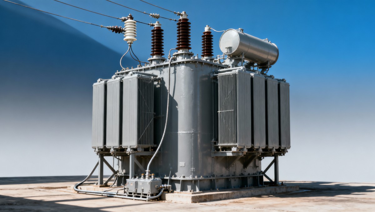
A useful coordination drawing shows the incoming circuit, arrester location, transformer bushing, connecting conductors, and earth connections. Showing these distances makes the protection assumptions easier to assess than an equipment list alone.
Altitude also needs explicit treatment. Reduced air density affects external air insulation, so bushings and clearances may require adjustment. Increasing the winding impulse rating alone does not resolve an external clearance problem.
Specify insulation by terminal, not just by transformer
A single impulse value on a transformer datasheet can conceal important differences between the high-voltage line terminals, neutral terminal, lower-voltage winding, and any tertiary winding. Use a terminal insulation schedule to remove that ambiguity.
Neutral insulation deserves particular attention. A winding designed with reduced neutral insulation relies on defined operating conditions. A solidly earthed neutral and a neutral that can become isolated do not necessarily experience the same voltage stress. State the permitted earthing arrangements and switching conditions before accepting the proposed neutral insulation.
For the lower-voltage winding, consider both surges arriving from its connected network and voltages transferred through the transformer. The high-voltage winding’s rating does not automatically establish suitable protection for every other terminal.
Bushing ratings must also fit the assembly. A suitable bushing cannot compensate for inadequate internal insulation, and adequate winding insulation cannot compensate for insufficient external clearances.
Define the impulse test beyond its peak voltage
The standard full lightning impulse is commonly described as a 1.2/50 μs waveform: a specified front time followed by a specified time to half-value on the tail. The governing standards define waveform evaluation and permissible tolerances. These details matter because insulation stress depends on the shape of the impulse as well as its peak.
For a 110 kV transformer, state the applicable full-wave test requirements and identify whether chopped-wave testing is required. A chopped impulse introduces a rapid voltage collapse that can impose different internal stresses. Full-wave and chopped-wave tests should not be treated as interchangeable evidence.
The agreed test program should address:
- Tested terminals and their assigned voltage levels.
- Impulse polarity and the prescribed sequence of applications.
- Full-wave and chopped-wave requirements, where applicable.
- Tap positions and treatment of other winding terminals during testing.
- Voltage and current measurements used to evaluate the response.
- Acceptance criteria and the procedure for investigating abnormal records.
Tap position affects the winding configuration and internal voltage distribution. The specification should require the standard’s applicable arrangements and identify any additional project requirement before manufacture. Leaving this decision until the factory test can create disagreement over whether the demonstrated configuration covers the intended service duty.
Acceptance requires more than a statement that no external flashover occurred. The test assessment should include the recorded voltage and current responses and any indications of internal insulation failure. Differences between traces require technical interpretation because the test circuit and external events can also affect the records.
Keep wind-farm transformer duties separate
A wind project may contain several transformer voltage classes. A turbine step-up transformer feeding a medium-voltage collection network has a different insulation duty from the main transformer connecting that network to a 110 kV grid.
For example, Jinshida Electric’s Transformer for Wind Power Generation is listed with capacities of 630–5000 kVA, a 0.69 kV low-voltage side, and 10, 20, or 35 kV high-voltage options. These ratings place it in the turbine or collection-system context; they do not establish a 110 kV grid-transformer capability.
When specifying the main grid transformer, identify the actual collection voltage, cable interfaces, earthing arrangement, and protection on that side. References to IEC 60076 across different products do not mean that those products share the same insulation class or impulse test duty.
Write a clause suppliers can price and demonstrate
A useful specification combines a completed insulation schedule with a defined test obligation. The following wording provides a structure; the project schedule supplies the actual values and terminal assignments:
Example procurement clause: “The transformer shall have the highest voltage for equipment and rated lightning impulse withstand voltages specified in the terminal insulation schedule. Dielectric design and testing shall comply with the contract edition of IEC 60076-3. The supplier shall identify the insulation levels of all line and neutral terminals, the proposed bushing ratings, and the applicable full-wave and chopped-wave test requirements. Before testing, the supplier shall submit the impulse test procedure, including terminal connections, tap positions, waveform requirements, measurements, and acceptance criteria. The final report shall include the measured test parameters, oscillograms, and assessment of results.”
Add the selected high-voltage impulse level explicitly. If the project adopts Um = 123 kV and 550 kV peak for its line terminals, show both values in the schedule. Avoid relying on “standard insulation” or “manufacturer’s usual practice,” which can produce quotations based on different assumptions.
Specify factory witnessing and document review requirements when placing the order. Any proposed use of previous test evidence should identify its contractual basis and demonstrate its relevance to the offered design.
Compare evidence as carefully as ratings
Two offers stating the same impulse withstand voltage may still differ in neutral insulation, chopped-wave testing, bushing selection, test coverage, or documentation. Resolve those differences before treating the offers as technically equivalent.
Request a completed terminal insulation schedule, a standards compliance statement, a clear deviations list, the proposed test program, and the assumptions used for insulation coordination. The final test report should identify the transformer and tested configuration, so the evidence can be linked to the supplied equipment.
The next step is to place the system voltage basis, terminal schedule, arrester arrangement, and test requirements beside one another. Any mismatch between them should become a specific technical query before the specification is released for purchase.

Get a Quote
Regardless of whether you require general advice or specific support, we are happy to help you.
Send Us Your Inquiry Today

Jinshida Electric remains committed to contributing to global energy development through professional manufacturing and superior service.