





Can you change a 35 kV transformer's tap position while energized?
A voltage reading is drifting outside the preferred operating band, production is running, and shutting down the transformer would interrupt the site. Can you change a 35 kV transformer's tap position while it is energized? Only if it has an on-load tap changer designed for energized operation, and the proposed change is permitted by the manufacturer’s instructions and site operating procedures.
For a 35 kV transformer equipped with a de-energized tap changer, the answer is no—even when the secondary load has been disconnected. The voltage rating alone does not establish whether energized tap changing is allowed. What matters is the installed tap-changing equipment, its condition, and the transformer’s operating arrangement.
This distinction is worth checking before anyone reaches for a handle or issues a remote command. Confusing the two tap-changer types can turn a routine voltage adjustment into an internal fault, equipment damage, or serious injury.
The deciding factor is the tap changer—not “35 kV”
Transformers adjust their voltage ratio by selecting different winding connection points, called taps. However, the mechanisms used to select those taps do not all have the same switching capability.
The term “off-load tap changer” deserves particular caution. It is sometimes used informally for a de-energized tap changer, but it can sound as though opening the secondary breaker is sufficient. No load and no voltage are different conditions. Use the manufacturer’s definition rather than relying on informal terminology.
Why a de-energized tap changer cannot be moved live
A de-energized tap changer is intended to select a winding connection when the transformer is electrically isolated and safe to work on. It does not have the switching arrangement needed to manage an energized transition between taps.
Moving its contacts while voltage is present can interrupt current or create an unintended connection between winding sections. Depending on the design and contact movement, the result may include arcing, contact damage, short-circuited turns, or an internal transformer fault. In oil-filled equipment, an internal arc can also generate gas and pressure.
An open secondary breaker does not remove these hazards. If the primary remains energized, the transformer still has winding voltage and draws excitation current. Other connections may also provide backfeed, particularly at sites with generators, renewable generation, interconnected buses, or auxiliary supplies.
Do not treat switching off the tap-changer motor supply as transformer isolation, either. Control power and the main electrical circuit are separate matters. A stationary mechanism can still be connected to energized windings.
How an OLTC makes energized adjustment possible
An on-load tap changer is specifically designed to transfer between adjacent taps while maintaining service. Depending on its design, it uses transition resistors or reactors, together with a coordinated switching sequence, to manage the temporary connection between taps. Some designs interrupt switching current in vacuum interrupters.
That capability is engineered into the complete assembly. It cannot be inferred from the presence of a motor drive, a remote-control panel, or a numbered position indicator. Nor does an OLTC designation mean every action involving the mechanism is safe while energized.
Normal electrical operation from an approved control point is different from opening a drive cabinet, defeating an interlock, inspecting internal parts, or manually manipulating a mechanism. Those activities may require separate isolation and maintenance controls.
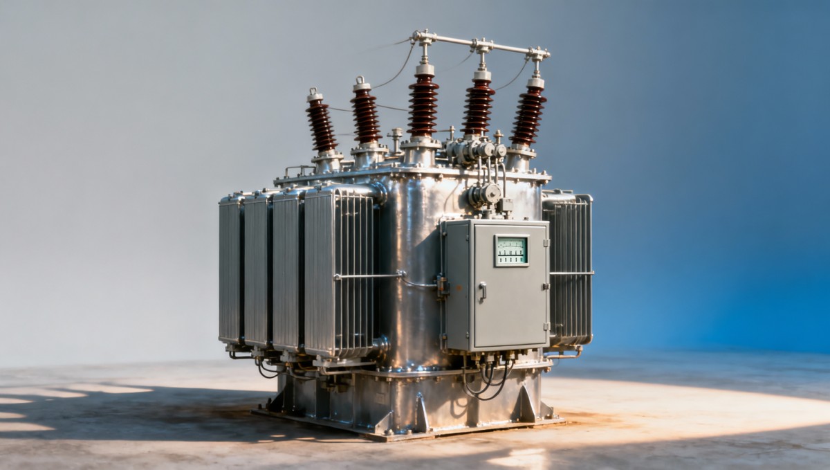
For operators, the useful visual comparison is between the equipment identification, the external mechanism, and the approved control diagram. Appearance alone is not a reliable way to classify the tap changer.
Before authorizing an energized change on a 35 kV transformer
The following checks support an operating decision; they are not a switching instruction. Actual operation must follow the equipment manual, site procedures, and the responsible electrical authority’s authorization.
Confirm the equipment identity
Match the transformer asset number with its nameplate, tap-changer nameplate, drawings, and operating manual. Look for an explicit statement that the installed device is an on-load tap changer. A generic manual for a similar transformer is not enough, especially if the unit has been refurbished or its controls modified.
Also verify the tap range, number of positions, step size, and which winding carries the taps. If identification plates are unreadable or documents conflict, pause the adjustment and obtain clarification.
Check whether operation is currently permitted
An OLTC can be suitable for energized use yet unavailable for operation in its present condition. Relevant checks include:
- Transformer and tap-changer alarms, protection indications, and outstanding defects.
- Load current and other operating conditions against the manufacturer’s limits.
- Drive health, position indication, and any incomplete-operation signal.
- Control mode, local/remote selection, and the status of automatic voltage regulation.
- Applicable maintenance restrictions, operation-count limits, or duty restrictions.
A protection alarm or inconsistent position indication is not something to bypass because the outgoing voltage needs correction. Investigate the condition before proceeding.
Understand what the voltage command will actually do
Do not assume that a higher tap number raises the secondary voltage. Tap numbering and the meaning of “raise” or “lower” depend on the transformer and control scheme.
For example, with fixed primary voltage and taps on the high-voltage winding, selecting more effective primary turns generally reduces secondary voltage. A control panel may nevertheless label commands according to the regulated bus response rather than winding turns. The approved tap table and control documentation settle the question.
If transformers operate in parallel, a tap change also affects load sharing and circulating current. Parallel-control logic, master/follower arrangements, or other coordination requirements must be checked before an individual unit is adjusted.
Voltage is low: is changing the tap actually the right response?
A low reading creates understandable pressure to act quickly, especially when motors are struggling or sensitive equipment is alarming. But a tap change corrects a voltage ratio; it does not repair a loose connection, an overloaded feeder, a faulty measurement circuit, or every upstream supply problem.
Before changing a 35 kV transformer’s setting, establish whether the reading is credible and where the voltage deviation occurs. Compare approved metering points, assess whether the condition affects all phases, and review loading and upstream voltage trends. A sudden phase imbalance or abrupt voltage change deserves investigation rather than an automatic tap correction.
Also consider what happens when demand falls. Raising voltage during a temporary peak may leave the downstream system too high later. Automatic voltage regulation should use appropriate setpoints, deadbands, and time delays so that the tap changer does not repeatedly respond to short-lived fluctuations.
Repeated “hunting” between positions is a control or system issue to investigate, not a reason to keep issuing manual commands.
If the transformer has a de-energized tap changer
In this case, the solution is a planned outage—not a faster way to move the selector. Qualified personnel need an approved switching and work plan that addresses every possible source of energization and the site’s electrical safety requirements.
That plan normally covers source isolation, prevention of reconnection, verification of absence of voltage, and grounding or earthing as required. Appropriate work boundaries, permits, and protective measures must be established before the tap mechanism is accessed. The specific sequence depends on the installation and must not be improvised from a general article.
Once the transformer has been made safe, adjustment must follow the manufacturer’s instructions, including correct engagement and locking of the selected position. Required checks before return to service may include position verification and electrical tests appropriate to the work performed.
Document the original position, the new position, the reason for the adjustment, and the authorized return-to-service checks. A clear record prevents the next shift from trying to explain a voltage change without knowing what was altered.
What to watch after an authorized OLTC operation
After a permitted energized tap change, confirm that the equipment has reached a valid position and that the measured voltage response matches the expected direction and approximate magnitude. Follow the manufacturer’s completion indication rather than assuming the mechanism has finished after a fixed waiting period.
Monitor the relevant voltage, loading, alarms, and—for parallel units—load sharing. If the drive stalls, indications disagree, an abnormal alarm appears, or voltage behaves unexpectedly, stop further commands and escalate under the site’s abnormal-operation procedure.
Do not repeatedly jog the mechanism, force a handle, or reverse commands in an attempt to clear an uncertain state. An incomplete transition requires equipment-specific assessment.
Specify the tap-changing requirement before purchasing
For replacement equipment or new projects, “voltage adjustment required” is not a complete specification. State whether adjustment must occur during service, the expected supply variation, the regulated voltage target, and any parallel-operation requirements. A transformer intended for occasional seasonal adjustment may need a different arrangement from one serving a frequently varying supply.
Jinshida Electric Power Technology Co., Ltd. develops and manufactures power transmission and distribution equipment. When discussing a transformer application, include the required tap-changer type and control philosophy alongside capacity, voltage ratio, and installation conditions.
For a separate 20 kV distribution application, its 20kV/0.4kV Oil-Immersed Power Distribution Transformer addresses a different voltage-conversion requirement from a 35 kV unit. Its tap-changing capability must be confirmed from the specified configuration; neither its product name nor its oil-immersed construction establishes permission for energized adjustment.
The answer to carry into the control room
A 35 kV transformer may have its tap position changed while energized only when the installed tap changer is designed for that duty and all applicable operating conditions are satisfied. A de-energized tap changer must not be moved live, even with the secondary load disconnected.
If the tap-changer type, equipment condition, or operating authority is uncertain, leave the position unchanged until it is verified. Protecting continuity of supply matters—but not at the cost of turning a manageable voltage problem into a transformer failure.

Get a Quote
Regardless of whether you require general advice or specific support, we are happy to help you.
Send Us Your Inquiry Today

Jinshida Electric remains committed to contributing to global energy development through professional manufacturing and superior service.