





When is one three-phase transformer preferable to three single-phase units?
One three phase transformer is usually preferable when space, installation simplicity, and total installed cost matter more than replacing individual phases. In an industrial substation, commercial building, or renewable energy installation, a single integrated unit can reduce the number of foundations, external connections, and separate assemblies. It is often the practical choice when the complete transformer can reach the site and an outage can be covered by another supply or an acceptable replacement plan.
Three single-phase units become more attractive when transport restrictions, lifting limits, or phase-by-phase replacement dominate the decision. A compact transformer is not necessarily the better solution if it cannot pass through the access route or would leave a critical facility waiting too long for a replacement. The useful comparison is therefore between two complete installations with the same electrical duty—not simply one enclosure versus three.
What changes when three phases share one assembly?
An integrated three-phase transformer combines the phase windings within one coordinated magnetic and mechanical assembly. Core arrangements vary, but many designs share magnetic paths between phases. A bank of three single-phase transformers uses three separate magnetic assemblies, connected externally to provide a three-phase supply.
Both arrangements can perform the same basic voltage-conversion task. Neither is inherently limited to a particular application simply because of its configuration. Voltage ratio, frequency, winding connection, insulation level, impedance, and thermal rating still have to match the system.
Capacity comparisons must also use the same basis. For a balanced bank of three equally rated single-phase transformers, the total three-phase rating is the sum of the three unit ratings. Comparing one integrated transformer against only one member of the bank produces a misleading price, weight, and loss comparison.
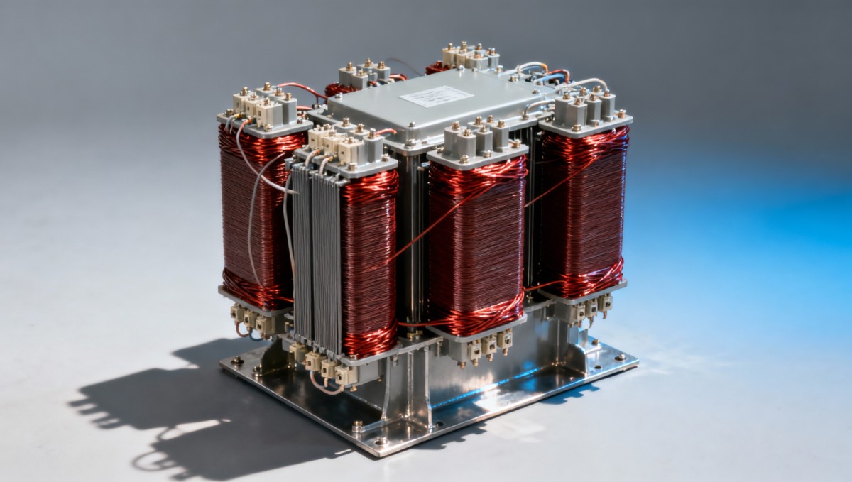
Where one integrated transformer usually makes more sense
A constrained electrical room or compact substation
In a building with limited electrical-room space, the transformer footprint affects more than equipment placement. It influences cable routing, ventilation, working clearances, access doors, and the ability to remove equipment later. One integrated assembly often makes this layout easier than accommodating three separate units and their interconnections.
The advantage must be checked on an installation drawing. A smaller equipment outline does not automatically mean a smaller room: cooling clearances, enclosure requirements, termination access, and maintenance space remain necessary. Compare the complete installed envelope rather than catalog dimensions alone.
A site where straightforward installation has real value
A single assembly generally reduces the number of separate items to position, secure, and interconnect. This can simplify civil works and site wiring, especially where labor access is difficult or the construction schedule leaves little room for connection changes.
Factory-completed internal connections also reduce some field assembly work. They do not remove commissioning obligations. Ratio, winding connection, phase sequence, insulation condition, protection settings, and grounding arrangements still require verification before energization. The benefit is fewer site interfaces, not permission to shorten acceptance testing.
A facility with another way to carry essential loads
An integrated unit is easier to justify when the facility already has a second transformer, an alternative feeder, or another suitably rated supply arrangement. In that situation, phase-level replacement may offer less operational value than reduced installation complexity.
The alternative supply must actually support the required loads. A second transformer on the drawing is not sufficient if its spare capacity, switching arrangement, or upstream supply cannot cover the outage. For hospitals and data centers, configuration decisions should follow the continuity architecture rather than treating either transformer arrangement as inherently redundant.
Check the loss advantage against the actual load profile
A shared magnetic structure can reduce material requirements and may give an integrated transformer lower losses than an equivalent bank. However, lower losses are a design outcome, not a guaranteed property of the configuration. Core material, winding design, operating temperature, efficiency specification, and loading all influence the result.
Request guaranteed no-load and load losses for both proposals. For the single-phase bank, add the losses of all three units. Confirm that the figures use equivalent reference temperatures, rating bases, and operating conditions before comparing them.
No-load losses occur whenever the transformer is energized, including lightly loaded periods. Load losses increase approximately with the square of current, with temperature and other effects also influencing the result. A continuously energized but lightly loaded installation may therefore favor a different loss balance from a heavily loaded production facility.
Renewable energy sites illustrate the distinction. Output may change substantially during the day, while the transformer can remain energized outside generating hours. Evaluating only full-load efficiency misses part of the energy cost. Use representative operating hours and loading levels, then include the resulting energy cost in the comparison.
When transport and replacement favor separate units
Transport constraints can overturn an otherwise attractive integrated design. The limiting factor may be a bridge load rating, road geometry, tunnel clearance, building entrance, or crane capacity at the required lifting radius. These constraints become particularly important as transformer ratings and shipping weights increase.
Three smaller shipping loads may reach a site that cannot accept one complete assembly. Nevertheless, obtain actual shipping dimensions and weights: dividing the electrical rating by three does not reliably predict transport mass. Packaging, accessories, cooling equipment, and any permitted shipping disassembly also affect the delivery plan.
Separate units can offer a maintenance advantage where a compatible single-phase spare is available. Compatibility means more than matching kVA and nominal voltage. Ratio, tap settings, polarity, impedance, insulation level, terminal arrangement, and connection suitability must support operation with the remaining units.
That advantage weakens if the spare is not stocked or replacement still requires a lengthy outage. Conversely, an integrated transformer can be a practical choice where an interchangeable complete spare is nearby. Compare credible restoration times, including fault investigation, delivery, installation, testing, and re-energization—not just the time needed to disconnect the damaged equipment.
Three units do not automatically provide redundancy
A bank normally needs all three units to deliver its intended three-phase rating. Losing one unit can interrupt the supply, and protection may disconnect the whole bank. Separate construction provides replacement flexibility; it does not guarantee continued service after a fault.
A delta-delta bank can, under suitable conditions, operate in open delta with two transformers. With the two remaining units retaining their original ratings, the available bank capacity is approximately 57.7% of the original closed-delta capacity. This is not a general option for every connection arrangement, and it requires engineering review of loading, voltage performance, protection, and grounding.
Keep dry-type versus liquid-filled construction separate from the phase decision
Choosing one integrated unit does not determine the insulation system. Dry-type and liquid-filled construction introduce separate questions about fire performance, cooling, environmental exposure, containment, and maintenance. A fair configuration comparison should avoid attributing every benefit of one insulation system to the number of transformer units.
For an indoor distribution application, the 33kV Cast Resin Dry-Type Distribution Transformer is a relevant option to evaluate. The supplied product information describes cast-resin insulation, copper windings, a grain-oriented silicon-steel core, temperature protection, and a 0.4 kV low-voltage output. These features relate to installation and operating requirements, while the integrated configuration addresses footprint and connection complexity.
Dry-type construction avoids insulating-oil leakage, but it still needs suitable ventilation, clearances, enclosure protection, and fire assessment. Confirm the exact high-voltage rating, insulation coordination, capacity, and tap arrangement on the project datasheet. The supplied information contains differing voltage and capacity references, so those details should not be treated as interchangeable specifications.
The listed forced-air overload capability also needs operating limits. It should not be treated as unrestricted continuous spare capacity. Ambient temperature, fan availability, winding temperature, loading duration, and the manufacturer’s approved loading guidance determine whether such operation is appropriate.
Compare complete proposals before choosing
Two quotations are only comparable after their electrical duties and installation boundaries are aligned. A lower transformer purchase price can disappear once additional foundations, buswork, protection, transport, or spare inventory are included.
- Define one common electrical specification. Use the same total three-phase kVA, voltage ratio, frequency, winding connection, tap range, insulation requirements, and impedance target. Include harmonics, unbalanced loads, and motor-starting duty where relevant.
- Test delivery and removal routes. Check shipping dimensions, weights, lifting arrangements, access openings, and future removal space. The route must work for replacement as well as initial construction.
- Price the installed system. Include civil works, interconnections, terminations, protection, cooling provisions, commissioning, and any containment required by the selected construction.
- Evaluate operating energy. Compare guaranteed losses against the expected loading profile rather than relying on a general efficiency claim.
- Write an outage-recovery plan. Identify the actual spare, its compatibility, replacement lead time, and how essential loads will be supplied during the interruption.
Protection and grounding deserve specific review when changing between configurations. Equal voltage and kVA ratings do not guarantee identical zero-sequence behavior, fault response, or inrush characteristics. Core construction and winding connections can affect system performance, so the selected arrangement must be checked against the network rather than substituted solely on nameplate capacity.
Prefer one integrated transformer when its delivery is feasible, its installed layout and losses are favorable, and whole-unit replacement fits the site’s continuity plan. Prefer separate single-phase units when smaller transport loads or a verified phase-replacement strategy solve a more important constraint. The deciding evidence is the site layout, guaranteed performance data, and a workable restoration plan—not the number of enclosures alone.

Get a Quote
Regardless of whether you require general advice or specific support, we are happy to help you.
Send Us Your Inquiry Today

Jinshida Electric remains committed to contributing to global energy development through professional manufacturing and superior service.