





How power transformer manufacturers demonstrate short-circuit strength
Power transformer manufacturers demonstrate short-circuit strength through a traceable combination of fault-duty calculations, winding and support design, manufacturing records, and applicable test evidence. IEC 60076-5 provides a framework for assessing the thermal and dynamic effects of external short circuits. A credible demonstration connects the specified network conditions to the actual transformer construction, with clear acceptance criteria and evidence that the manufactured unit matches the assessed design.
A nameplate impedance or a statement that a transformer is “short-circuit proof” leaves essential questions unanswered. The evidence must establish the fault current, its asymmetrical peak, the duration of current flow, and the winding configuration under evaluation. Thermal withstand and mechanical withstand require separate assessments because their controlling conditions differ.
Define the fault duty before assessing the design
The starting point is the electrical network at the transformer terminals. Relevant inputs include system voltage, available source fault level, source impedance, transformer impedance, earthing arrangements, and contributions from other connected sources. The calculation must cover the applicable external fault types and winding connections rather than assume that a three-phase terminal fault produces every governing stress.
For a simplified balanced fault, symmetrical current follows the relationship I = V / Z, using consistent phase quantities and the combined source and transformer impedance. Treating the source as infinitely strong removes its impedance and increases calculated current. That assumption needs to be explicit; a calculation based on a finite source fault level cannot automatically substantiate performance on a stronger network.
Percentage impedance also requires context. Its effect on fault current depends on the rating base, tap position, impedance tolerance, and system contribution. Two transformers with the same percentage impedance can have different current duties and very different mechanical margins. Where several windings feed a fault, individual winding currents and their phase relationships must be resolved.
Fault duration must correspond to the specified protection clearing duty, including any required backup protection condition. The first current peak is governed strongly by asymmetry and the circuit resistance-to-reactance relationship. A short clearing time reduces heating, but substantial winding movement can begin during the first peak.
Thermal withstand: connect current duration to conductor temperature
The thermal assessment establishes whether fault heating remains within the applicable limits for the conductor and insulation system. Its inputs include conductor material, effective cross-sectional area, initial winding temperature, fault-current magnitude, and duration. An assessment starting from an unrealistically cool winding can overstate the available thermal margin.
The familiar I2t relationship is useful for understanding accumulated heating, but a defensible calculation also accounts for conductor resistance changing with temperature and uses the method applicable to the design. Where current changes during the fault, the relevant quantity is the integral of current squared over time. A quoted withstand duration has little meaning without its associated current.
Local details deserve attention. Reduced conductor sections at connections, transpositions, and leads can create limitations that a winding-average calculation misses. Evidence should identify the conductor sizes used in the calculation and connect them to controlled drawings. Insulation temperature limits must correspond to the actual materials and the applicable standard provisions.
Mechanical strength is determined by the winding structure
Electromagnetic forces arise from the interaction between winding current and leakage magnetic flux. For a fixed geometry, force varies approximately with current squared. Consequently, a modest increase in peak current can produce a substantially larger force demand. Mechanical assessment therefore needs the specified asymmetrical peak, not only the symmetrical RMS current used in many fault-level summaries.
Radial forces act across the winding thickness. In a common concentric arrangement, the inner winding experiences inward loading while the outer winding experiences outward loading. The inner winding requires resistance to buckling, including deformation between supports; the outer winding requires adequate hoop strength. Conductor strength alone does not establish either margin because support spacing, winding geometry, and manufacturing imperfections affect stability.
Axial forces act along the winding height and become especially significant around winding ends, tapping regions, and locations where ampere-turns are unbalanced. End blocks, pressure rings, clamping structures, and conductor support arrangements must carry these forces through a defined structural path. Small differences in winding height or axial alignment can change the force distribution.
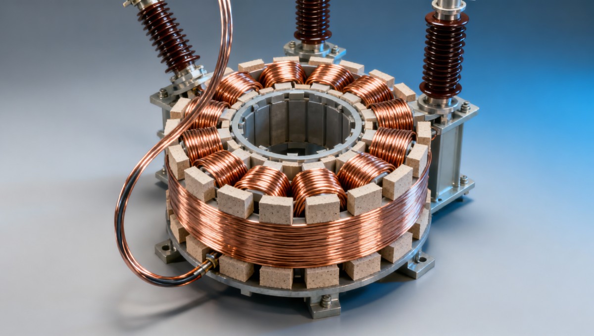
A useful design illustration shows the winding cross-section, radial and axial force directions, and how loads pass through spacers and clamping components. A general assembly photograph rarely reveals enough to explain whether an unsupported conductor span or an end-support interface governs the design.
Finite-element analysis can resolve leakage fields and local forces, but its credibility depends on geometry, material properties, boundary conditions, and validation. A coloured stress plot without stated current, tap position, contact assumptions, or allowable stresses provides limited evidence. Buckling assessments also need to address imperfections; an ideal circular winding model can overestimate stability.
What a short-circuit test report actually establishes
A short-circuit withstand test provides direct evidence for the tested transformer under the recorded conditions. Its relevance depends on the identity of the test object, the applicable standard edition, the circuit arrangement, the tap positions, and the achieved current waveforms. A laboratory certificate stating only “passed” does not expose these details.
The report needs to distinguish the symmetrical current, the first asymmetrical peak, and the duration of each application. The connection between the tested winding arrangement and the proposed service duty must also be clear. Testing one winding combination on a multiwinding transformer does not establish every other combination without supporting assessment.
Acceptance rests on the complete requirements of the applicable standard and contract, including the prescribed measurements, tests, and inspections. Universal reactance-change limits should not be copied into a specification without confirming their applicability to the transformer category and winding construction.
Routine factory tests serve a different purpose. Ratio, resistance, loss, impedance, and dielectric results help establish manufacturing conformity and electrical performance. They do not reproduce the mechanical loading of a short-circuit withstand test. Their value increases when they form part of a consistent evidence package tied to the assessed design.
When a reference test applies to a new transformer
A previous successful test can support a proposed design when the applicable assessment route permits it and the technical comparison is justified. Similar power rating or voltage class is insufficient. The comparison needs to establish whether the proposed winding experiences comparable stresses and has comparable or greater strength at the relevant locations.
Useful comparison parameters include winding type, conductor dimensions and mechanical properties, winding diameter and height, radial build, axial support spacing, clamping arrangement, insulation construction, impedance, and fault duty. Differences in tapping sections and lead exits deserve explicit treatment because they introduce local forces and unsupported lengths.
Scaling requires particular care. A larger conductor does not necessarily compensate for a larger winding diameter or a longer unsupported span. Likewise, increasing impedance can reduce fault current while changes in leakage-field geometry alter local force concentration. Each claimed improvement needs to connect to the failure mode it addresses.
A reference-test assessment is strongest when it identifies every material difference, quantifies the resulting stress changes, and explains the remaining margin. Where the proposed construction falls outside the validated design range, additional analysis or testing must address that gap. An unexplained statement that both units belong to the same series leaves the comparison incomplete.
Manufacturing records connect the calculation to the delivered unit
Short-circuit performance depends on construction details that are difficult to infer from final electrical results. Conductor mechanical properties, winding tension, spacer positioning, insulation drying, winding sizing, and clamping condition all influence how the structure responds to fault forces.
Cellulose insulation changes dimension during processing and under compression. The winding assembly process therefore needs controlled drying and compression conditions, with records showing how the specified final dimensions and clamping state were achieved. An applied tightening torque alone does not establish retained winding pressure because friction and insulation settlement affect the result.
Traceability should connect material certificates, winding records, dimensional inspections, and final assembly documentation to the transformer serial number. Design changes also require control: substituting a conductor temper, changing a spacer pattern, or revising an end-support arrangement can invalidate assumptions used in an earlier assessment.
Transport and installation introduce a further boundary. Significant shock, internal movement, or reassembly can alter the condition established at the factory. Where shipment arrangements or recorded events justify additional verification, the assessment needs suitable baseline measurements and defined investigation criteria. Frequency-response measurements can support comparison, but interpreting a difference requires consistent test connections and engineering review.
Storage connections require the same fault-duty discipline
At a storage connection, the associated transformer assessment must distinguish grid-fed fault current from converter-fed contributions. A 1MW/2MWh Liquid Cooling Container Energy Storage System has a stated power and energy capacity, but those figures do not establish transformer short-circuit duty. The connection voltage, transformer impedance, converter fault-current behaviour, network strength, and protection clearing times determine the relevant assessment.
Converter current limitation does not remove the grid contribution to a fault on the transformer’s converter-side terminals. Conversely, treating the converter as an unrestricted conventional source can misrepresent its contribution. The fault study needs the applicable converter data, transformer connection arrangement, and credible operating configurations, including parallel sources where present.
The final technical record should identify the accepted network duty, the corresponding thermal and mechanical assessments, the test evidence supporting the construction, and any conditions attached to that acceptance. If network reinforcement, protection changes, or added parallel generation later exceeds those conditions, the original demonstration requires reassessment against the revised duty.

Get a Quote
Regardless of whether you require general advice or specific support, we are happy to help you.
Send Us Your Inquiry Today

Jinshida Electric remains committed to contributing to global energy development through professional manufacturing and superior service.