





How grounding transformer impedance changes earth-fault current
How Grounding Transformer Impedance Changes Earth-Fault Current
Grounding transformer impedance is not a secondary detail to be checked after the main transformer and switchgear have been selected. In an otherwise ungrounded medium-voltage system, it is one of the main factors that decides what happens during a single line-to-ground fault: whether the fault current is high enough for protection to see it, low enough to avoid unnecessary equipment damage, and controlled enough to prevent sustained overvoltage on healthy phases.
For technical evaluators, the difficult part is that “impedance” can mean different things in a tender document. A transformer may have a percentage impedance stated for normal load or short-circuit performance, while the earth-fault study requires the zero-sequence impedance of the grounding path. These values are related to transformer design, but they are not interchangeable. Treating them as the same is a common source of incorrect fault-current calculations.
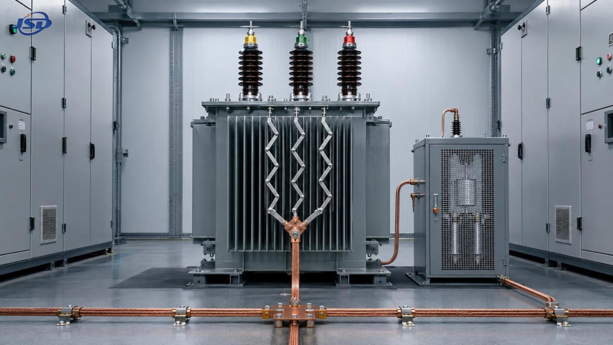
A three phase grounding transformer is typically installed where the existing system transformer does not provide an accessible neutral point. A zig-zag or wye-delta grounding transformer creates that neutral reference. An impedance device—most often a neutral grounding resistor, though reactors are also used in some schemes—then determines how much current can flow from the system into an earth fault.
The fault-current path is the starting point
During a phase-to-earth fault, current does not simply travel through the phase conductor and return through soil. In a grounded three-phase network, it follows a zero-sequence loop: the faulted phase, the earth-return network and bonding conductors, the grounding transformer neutral, its windings, and the upstream network representation. Every part of that loop contributes impedance.
For a bolted single line-to-ground fault, engineers commonly express the initial symmetrical current in simplified form as:
ILG = 3Vph / (Z1 + Z2 + Z0 + 3Zf)
Here, Z1, Z2, and Z0 are the positive-, negative-, and zero-sequence impedances seen from the fault location, while Zf represents fault-path impedance. In a resistance-grounded network, the neutral grounding resistor is usually a dominant part of the zero-sequence path. Depending on how data are presented, it may be included within Z0 or shown separately as three times the neutral impedance. The convention must be kept consistent throughout the study.
The practical consequence is straightforward: higher total grounding-path impedance produces lower earth-fault current; lower impedance permits more current. Yet selecting the highest available impedance is not automatically safer. If current falls below the reliable pickup range of the relay and current transformer arrangement, a persistent fault may remain energized. That is a protection problem, not an impedance-saving achievement.
Grounding transformer impedance and resistor impedance do different jobs
In most resistance-grounded installations, the neutral grounding resistor is intentionally chosen to control the earth-fault current. The grounding transformer itself must be designed to carry the corresponding zero-sequence current for the specified duration, commonly long enough for fault detection and breaker operation. Its winding impedance, however, still affects the final result and cannot be ignored.
A low-impedance grounding transformer coupled with a relatively low-resistance neutral path allows a larger ground-fault current. This can make conventional overcurrent protection easier to coordinate, but it also raises thermal and mechanical duty on the transformer, neutral resistor, cables, switchgear, and faulted equipment. It may also increase touch-voltage concerns if the earthing grid and bonding arrangement have not been evaluated as a complete system.
At the other end, a high-impedance path limits damage at the fault point and can reduce arc energy associated with ground faults. But protection then needs more careful engineering. Sensitive residual-current or zero-sequence protection, suitable CT selection, relay filtering, and coordination with capacitive charging current become more significant. In cable-rich networks, especially those with long MV feeders, the system’s phase-to-earth capacitance is not negligible. A grounding design that looks acceptable from transformer data alone can behave differently after the actual cable network is added.
This is why an evaluator should ask for the grounding transformer’s zero-sequence impedance or grounding-duty data, not merely its normal percentage impedance. The requested information should also state the intended neutral current, rated duration, system voltage, connection type, insulation level, and permitted temperature rise for the specified duty. A transformer that is adequate for a brief fault on paper may not suit a scheme with delayed backup protection.
Why the connection type matters as much as the impedance value
A zig-zag grounding transformer is widely used because its winding arrangement provides a neutral point while presenting low impedance to zero-sequence current and relatively high impedance to balanced positive-sequence load current. Under healthy three-phase conditions, the winding flux components largely cancel. Under an earth fault, the zero-sequence components add in the intended grounding path.
A wye-delta arrangement can also create a grounding point, but the delta winding must provide the internal circulating path required for zero-sequence current. The correct choice depends on voltage level, available space, system configuration, required thermal duty, harmonics, protection philosophy, and whether an auxiliary transformer function is needed. It is not sensible to specify one arrangement by habit alone.
One subtle issue is the relationship between the grounding transformer and the source transformer. A delta-connected source transformer can block zero-sequence current from passing upstream. In that situation, the local grounding transformer may become the principal return path for an earth fault on the downstream bus. Its impedance and neutral resistor therefore have a much more direct influence on the fault level than they would in a solidly grounded utility source system.
Selecting a target earth-fault current is a coordination exercise
The starting point should be a system study, not a preferred resistor rating. Engineers normally need the system one-line diagram, transformer vector groups, generator and inverter contributions where applicable, feeder lengths and cable types, existing grounding points, load characteristics, and protection settings. For renewable plants, collector-circuit cable capacitance and the grounding behavior of inverter step-up transformers deserve particular attention. A solar or wind project can change materially between early design and final cable routing.
The selected ground-fault current needs to satisfy several conditions at once:
- It must exceed the expected capacitive charging current by a suitable margin for the selected grounding method and protection philosophy.
- It must be high enough for primary and backup protection to detect a fault reliably at the furthest relevant location.
- It must remain within the short-time current capability of the grounding transformer, resistor, neutral conductor, switchgear, and earthing system.
- It must support acceptable relay coordination without causing an upstream device to trip before the local feeder protection.
- It must be reviewed against the project’s applicable IEC, IEEE, utility, or local grid requirements rather than assumed from a generic design.
There is no universal “best” earth-fault current. Industrial networks often favor controlled resistance grounding to balance continuity and equipment protection. A utility substation may follow a grounding approach driven by the network operator. Temporary power systems can be constrained by compact equipment layouts and limited fault-study information. The correct level is always tied to the actual system and the protection scheme that will operate on it.
Do not overlook impedance tolerances and installation details
Calculated current is only as good as the assumptions behind it. Transformer impedance has manufacturing tolerance, and neutral resistor value changes with temperature. Connection leads, busbar runs, cable screens, grounding conductors, and contact resistance all add to the real circuit. Usually these do not overturn a sound design, but they matter when relay pickup is close to the minimum available fault current.
A robust evaluation checks both ends of the range: maximum earth-fault current for equipment duty and minimum earth-fault current for protection sensitivity. The fault resistance assumption should be realistic as well. A metallic fault gives a useful maximum-current case, but many field faults involve some resistance. If the relay only operates for an ideal bolted fault, the scheme has little margin.
Physical installation can also undermine a good calculation. The neutral connection should be short, correctly rated, clearly identified, and protected from accidental bypass. The resistor enclosure needs appropriate ventilation and environmental protection. Where the grounding transformer sits in a compact substation, maintainable access to the resistor, neutral CT, test links, and terminal connections should be considered before the enclosure layout is frozen.
For distribution projects requiring an integrated enclosure, a solution such as the European-Type Compact Substation can be configured for high- and low-voltage distribution arrangements, metering, and transformer capacities from 100 kVA to 2500 kVA. Its suitability for a grounding scheme still depends on the actual neutral arrangement, transformer duty, internal clearances, heat dissipation, protection layout, and site conditions. A compact enclosure does not eliminate the need to verify the zero-sequence network.
Common evaluation mistakes
The first mistake is specifying a grounding transformer by voltage and kVA only. Grounding duty is not ordinary continuous load duty. The fault-current magnitude and duration must be explicit. A second is selecting a neutral grounding resistor without confirming that the transformer can carry the associated current for the required time.
Another recurring mistake is assuming that all earth faults are seen by phase overcurrent elements. In resistance-grounded systems, dedicated earth-fault protection is often necessary. Its performance depends on CT placement, residual connection accuracy, relay settings, and the minimum available fault current. The grounding system, CTs, relay logic, and breaker clearing time should be reviewed as one design package.
Finally, engineers sometimes focus only on limiting current and overlook temporary overvoltages. If grounding is too weak, an intermittent fault can produce unhealthy phase-to-earth voltage conditions on unfaulted phases. The consequences may include insulation stress and unreliable indication, particularly where cable capacitance is substantial. This is a reason to compare grounding alternatives using a proper network study rather than selecting an impedance from a catalog.
A practical review before release
Before approving a three phase grounding transformer, confirm the rated system voltage and connection, the required neutral current and duration, the transformer’s zero-sequence characteristics, the resistor or reactor value, and the calculated minimum and maximum earth-fault currents. Then compare those results with relay sensitivity, breaker clearing time, CT capability, enclosure thermal conditions, and the site earthing design.
Manufacturers with power transmission and distribution engineering capability can provide useful equipment data, but the final grounding arrangement must remain project-specific. Jinshida Electric Power Technology Co., Ltd. supports power equipment applications across grid, industrial, infrastructure, and renewable-energy environments, where reliable operation depends on matching equipment design to the actual network rather than relying on nominal ratings alone.
The key judgment is simple: grounding transformer impedance changes earth-fault current because it is part of the zero-sequence return path. But the design question is larger than “how much current will flow?” It is whether that current is controlled, detectable, thermally manageable, and properly coordinated from the fault point through to the protective device that must clear it.

Get a Quote
Regardless of whether you require general advice or specific support, we are happy to help you.
Send Us Your Inquiry Today

Jinshida Electric remains committed to contributing to global energy development through professional manufacturing and superior service.