





Evaluating Distribution Transformers for Data Center Uptime and Redundancy
Start With the Uptime Architecture, Not the Transformer Rating
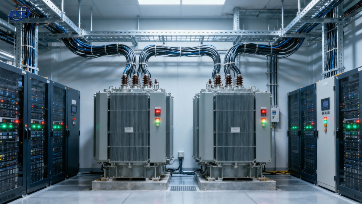
A distribution transformer for data centers should be evaluated as part of a power path, not as an isolated piece of equipment. A transformer with the correct MVA rating can still undermine availability if it becomes a common point of failure, overheats under nonlinear load, cannot be maintained without interrupting a critical bus, or does not coordinate properly with generators, UPS systems, and downstream protection.
For technical evaluators, the first question is therefore not “What transformer size is needed?” It is: “What failure can this transformer introduce into the selected redundancy topology?” The answer differs materially between a small enterprise facility with a single UPS train, a concurrently maintainable N+1 design, and a compartmentalized 2N or distributed-redundant architecture.
In a resilient design, each transformer must have a defined role in normal operation, generator operation, overload conditions, maintenance, and fault isolation. If its loss removes both the preferred and alternate supply to a critical load, redundancy on paper may not translate into usable redundancy in operation.
Map Transformer Placement Against Single Points of Failure
The placement of the transformer often matters more than a modest difference in efficiency or purchase price. A medium-voltage-to-low-voltage transformer feeding a single main switchboard may be fully acceptable for a noncritical building load. It is a much more consequential decision when that same board supplies multiple UPS modules, cooling plant controls, network rooms, or other loads needed to keep an IT environment online.
Evaluators should trace every power path from the utility service and on-site generation through the transformer, switchgear, UPS, power distribution units, and rack-level distribution. The exercise should identify whether a transformer, its protective device, a common bus section, or its cooling and monitoring dependencies can disable more than one redundant path.
A useful review asks four practical questions:
- Can one transformer failure remove both A-side and B-side power for any critical load?
- Can the transformer be isolated and maintained while the critical load remains supplied through an independent path?
- Does a downstream fault clear selectively, or can it trip the transformer primary device and take out an entire electrical block?
- During generator operation, does the transformer remain within acceptable voltage, thermal, and protection limits?
A common weakness appears when dual-corded IT equipment is fed from two downstream panels that eventually converge on the same transformer or low-voltage bus. The equipment may have two cords, but the upstream architecture still contains a shared dependency. Physical separation, independent protection zones, and independent transformer paths are more meaningful than simply counting panels or breakers.
For facilities designed around N+1 capacity, a transformer can be operated below full loading with a spare unit or spare capacity available elsewhere. That arrangement only improves uptime if transfer procedures, bus ties, interlocks, and protection settings permit the remaining equipment to carry the load safely. For 2N designs, the expectation is usually stronger: each side should support the designated critical load independently, including under expected operating constraints.
Size for the Electrical Load That Will Actually Reach the Transformer
Nameplate capacity remains essential, but it should be based on a defensible load model rather than on IT nameplate totals alone. The transformer sees a combination of IT load, UPS losses, cooling loads where applicable, auxiliary systems, future expansion, and the operational loading strategy for each redundant path. A facility may intentionally keep each transformer at a lower normal load so that another unit can absorb demand after a failure or maintenance event.
The load profile also matters. Data center load growth is often staged, while transformer selection tends to be made early in the project. Oversizing without examining light-load efficiency, excitation losses, space constraints, fault duty, and expansion sequencing can create unnecessary lifecycle cost. Undersizing can be worse: sustained high loading reduces thermal margin, narrows room for unexpected growth, and may complicate redundancy during an outage.
Technical review should distinguish among normal operating load, maximum expected load, contingency load, and generator-backed load. These figures may not be identical. A transformer that performs acceptably under utility supply may face a different voltage profile, fault-current contribution, and loading pattern when supplied by generators. The generator-transformer-UPS combination needs to be evaluated as a system, especially where several UPS units start, recharge batteries, or transfer operating modes during restoration.
Harmonics Are a Thermal and Reliability Issue
Modern IT power supplies and UPS front ends can create nonlinear currents, although the actual harmonic profile depends on the equipment and topology in use. Harmonic current increases losses in transformer windings and structural components, and it can raise temperatures beyond what a conventional sinusoidal-load assumption would predict. A transformer selected solely by kVA may therefore have insufficient thermal capability for its duty.
Ask for the assumptions behind the offered thermal design. The evaluation should cover expected harmonic spectrum, eddy-current loss allowances, neutral loading, derating methodology, winding hot-spot limits, and the manufacturer’s basis for any harmonic-capable rating. A claim that a unit is “suitable for data centers” is not a substitute for showing how the unit handles the actual nonlinear load and operating temperature.
Neutral design deserves the same attention. Triplen harmonics can accumulate in the neutral of certain low-voltage distribution arrangements. The transformer secondary configuration, neutral conductor sizing, downstream panel design, and protection approach must be reviewed together. Treating the transformer as a stand-alone purchase can leave this issue unresolved until late-stage commissioning.
Thermal Margin Should Be Evaluated Over Its Whole Operating Life
Transformer insulation ages in response to temperature and time. For a data center, thermal evaluation should extend beyond ambient temperature at delivery. Consider the installed room temperature, ventilation or liquid-cooling arrangement, elevation, dust exposure, airflow restrictions, seasonal conditions, expected load profile, and the possibility of a prolonged contingency state.
Dry-type transformers are often selected for indoor use where fire and oil-containment considerations influence equipment-room design. Their performance is closely tied to enclosure, ventilation, and room heat removal. A unit can meet its rating in a test environment yet operate with less margin when installed in a crowded electrical room with recirculating hot air or inadequate clearances.
Liquid-filled transformers can offer different thermal and capacity characteristics, but they introduce site-specific considerations involving fire protection, containment, environmental rules, access, and maintenance procedures. The correct choice depends on the building arrangement and risk strategy; neither type should be treated as inherently superior without examining the installed conditions.
Temperature monitoring should be specified for operational use, not merely for a local alarm. Winding and ambient temperature data, alarm and trip thresholds, fan status where applicable, and communications interfaces should fit the site’s electrical monitoring platform. The operations team needs a clear escalation path when temperatures rise: whether the response is load redistribution, cooling verification, maintenance inspection, or controlled capacity reduction.
Protection Coordination Determines Whether a Fault Stays Local
Transformer impedance and protection coordination strongly influence outage scope. Higher or lower impedance affects available fault current, voltage regulation, and how protective devices coordinate across the system. There is no universally correct impedance value for a data center. The correct selection follows a fault study and coordination study that includes the utility source, generators, transformers, switchgear, UPS input characteristics, and major downstream feeders.
Protection needs to clear faults quickly while preserving the greatest possible portion of the power system. If a secondary feeder fault causes an upstream transformer breaker to trip before the feeder protection operates, an isolated problem can become a broad outage. Conversely, overly conservative settings may expose equipment to excessive fault energy or delay clearing.
Request the information needed for system studies early: transformer impedance tolerance, vector group, inrush characteristics, available tap range, primary and secondary ratings, grounding arrangement, and protective-device recommendations. These values should remain controlled through procurement. A late substitution with materially different impedance or configuration can invalidate parts of the electrical study and force redesign of settings or equipment ratings.
Inrush also deserves attention when transformers are energized after a utility interruption or during restoration sequences. Protective relays and breaker settings must distinguish normal magnetizing inrush from a fault while still providing dependable protection. Where multiple transformers energize in sequence, the switching plan should be considered alongside generator capacity and UPS operating behavior.
Specify Maintainability and Monitoring as Part of the Transformer Package
Uptime is affected by the speed and certainty with which operators can identify deteriorating conditions. The procurement specification should define what information must be available, who owns the interfaces, and how alarms are integrated. Basic temperature indication alone may be insufficient for a high-availability facility.
Depending on transformer type and criticality, the evaluation may include winding temperature, enclosure or oil temperature, fan status, tap position, partial discharge monitoring, insulation condition indicators, moisture-related diagnostics, and event records from protection devices. Not every site needs every monitoring feature. The selection should follow the consequence of failure, maintenance philosophy, and the ability of the operations team to act on the data.
Maintainability also has a physical dimension. Confirm equipment access routes, lifting requirements, replacement clearances, cable termination access, ventilation clearances, and the practical time needed to isolate and replace a unit. A design that is electrically redundant but requires intrusive construction to replace a transformer has a weak recovery profile.
Factory acceptance testing and site testing should be aligned with the criticality of the installation. The objective is not simply to obtain test documents. It is to verify nameplate data, ratio, polarity or vector group, insulation condition, protection interfaces, communications, alarms, and the as-installed behavior of the complete electrical path.
Assess Storage and Backup Power as a Coordinated Architecture
Battery energy storage is sometimes considered to reduce generator dependence, support load transitions, or add operational flexibility. When it is connected within a data center electrical architecture, it changes the transformer evaluation. The transformer may see new bidirectional power flows, charging loads, inverter-generated harmonics, altered fault contribution, and different protection requirements.
For example, a containerized solution such as the 1MW/2MWh Liquid Cooling Container Energy Storage System combines LiFePO4 batteries, battery management, energy management, liquid cooling, fire protection, and monitoring in a 20-foot format. Its suitability for a particular site does not follow from the energy rating alone. Evaluators should determine where it connects, whether it supports critical loads or noncritical load management, how it coordinates with UPS and generator controls, and whether the transformer and switchgear are rated for the resulting operating modes.
Remote monitoring and standard communications options can simplify integration, but control responsibility must remain clear. During abnormal conditions, conflicting commands between an energy management system, UPS controls, generator controls, and building power management can create avoidable instability. The protection and controls design should define priorities for islanding, charging, discharge, load shedding, restoration, and manual override.
What to Ask Before Releasing the Purchase Order
A sound technical bid comparison goes beyond price, efficiency figures, and delivery time. It should show whether each supplier is responding to the same duty requirements and whether deviations have been made explicit. The most useful technical submittal will state ratings at the relevant ambient conditions, insulation and thermal assumptions, impedance and tolerances, harmonic capability, losses, sound limits where applicable, enclosure or fluid details, monitoring scope, test plan, drawings, and service requirements.
- Provide the one-line diagram and identify the transformer’s role in each normal, maintenance, and failure scenario.
- State the expected load profile, nonlinear-load assumptions, power factor, contingency loading, and growth plan.
- Confirm transformer configuration, grounding, impedance, tap arrangement, and protection-study inputs before final manufacture.
- Review room conditions, access, ventilation, fire strategy, and monitoring integration as part of the equipment decision.
- Require a documented commissioning sequence that tests transfer paths, alarms, protective operation, and restoration behavior without exposing critical loads to unnecessary risk.
The right transformer selection is the one that preserves the intended electrical architecture under ordinary operation and under credible faults, maintenance events, and restoration sequences. Capacity is only the entry point. Thermal durability, fault selectivity, operational visibility, and independence between redundant paths decide whether the transformer supports data center uptime or quietly limits it.

Get a Quote
Regardless of whether you require general advice or specific support, we are happy to help you.
Send Us Your Inquiry Today

Jinshida Electric remains committed to contributing to global energy development through professional manufacturing and superior service.