





Why Data Centers Need Distribution Transformers Built for Continuous Loads
Data centers need transformers designed around continuous loading because their electrical demand rarely follows the operating pattern assumed for ordinary commercial buildings. Servers, storage, network equipment, cooling systems, and power-conversion equipment may run at substantial load for every hour of the year. A transformer that is adequate for intermittent or lightly loaded service can face higher thermal stress, greater loss-related heat, and less operating margin when placed upstream of critical IT loads.
For facility planners, the issue is not simply whether a transformer can carry its nameplate rating. The more useful question is whether it can maintain acceptable temperature rise, voltage performance, efficiency, and service life while operating near its expected load profile for long periods. In a data center, a transformer is part of the uptime chain. Its behavior affects downstream switchgear, UPS systems, cooling equipment, and ultimately the availability of computing capacity.
Continuous Load Changes the Selection Logic
Many electrical systems experience pronounced peaks and troughs. An office building may reach high demand during working hours and then fall back significantly overnight. Manufacturing sites may have shift-based production cycles. A data center can have some variation, particularly during staged deployment or maintenance, but its baseline load is usually much higher and more persistent.
This matters because transformer heating is cumulative. Load losses increase as current rises, and the heat generated in windings, connections, and insulating materials must be removed continuously. Oil temperature, winding hot-spot temperature, ambient conditions, ventilation, and cooling arrangement all influence whether that heat remains within the design limits. A transformer may tolerate a short overload, yet that does not make sustained high utilization a sound normal operating strategy.
Thermal margin is therefore more important than a simple comparison between planned demand and rated kVA. A load forecast should account for the IT load, cooling demand, UPS losses, auxiliary systems, future rack deployment, and the way redundant power paths are intended to operate. A design that appears comfortable under a normal operating calculation may become constrained when one transformer, feeder, or power module is unavailable and the remaining equipment carries a larger share.
For a distribution transformer for data centers, engineers commonly assess at least three loading conditions: normal operation, expected peak operation, and the highest credible load during a contingency. The last condition is often where transformer sizing decisions become difficult. N+1 or 2N electrical architecture can improve resilience, but only when each remaining path has sufficient thermal and electrical capacity for its assigned contingency duty.
Heat Is Not Just a Transformer Maintenance Concern
Transformer temperature is sometimes treated as a maintenance issue to be handled after installation through inspections and alarms. In a continuously loaded facility, it should be addressed much earlier, during electrical and physical design. Excess heat affects insulation aging and can reduce the margin available for high ambient conditions, restricted airflow, or a gradual increase in IT demand.
Location makes a practical difference. An outdoor transformer enclosure exposed to solar gain and high seasonal temperatures has a different thermal environment from an indoor unit in a conditioned electrical room. Indoor installations introduce their own constraints: room ventilation, heat rejection, fire protection requirements, access for inspection, and the effect of transformer heat on surrounding equipment. A transformer with acceptable performance on paper can still operate under undesirable conditions if the installation does not support its cooling assumptions.
Continuous duty also makes temperature monitoring more valuable. Top-oil temperature and winding temperature indicators can help operators identify loading changes, cooling problems, or abnormal thermal behavior before a protection trip occurs. Monitoring does not replace proper sizing, but it allows the operating team to confirm whether the original design assumptions remain valid as capacity is added over time.
Oil-immersed transformers require particular attention to fluid condition, seals, radiators, and the installation environment. The choice of insulating fluid may also affect fire-safety planning and environmental requirements. Where an oil-immersed unit is appropriate, the facility team should evaluate the transformer as part of the complete installation, including containment, protection coordination, clearances, and maintenance access, rather than as an isolated item of equipment.
Efficiency Matters More When the Transformer Rarely Rests
Transformer losses are present throughout operation. No-load loss occurs whenever the transformer is energized, while load loss rises with the current supplied to the load. In a facility designed for 24/7 service, both categories contribute to operating energy use and to the heat that must be managed in the electrical space.
This does not mean that the lowest quoted loss value always produces the best selection. Loss figures need to be compared at the relevant voltage, frequency, capacity, temperature reference, and load point. A transformer selected for a future final load may spend years operating far below that load if data hall buildout occurs in stages. Conversely, a unit selected too tightly around an initial deployment can be exposed to unfavorable loading once more racks and cooling capacity are added.
The useful calculation is a lifecycle one: expected loading over time, energy cost, required redundancy, cooling impact, maintenance approach, and planned expansion should all be considered together. For example, an oversized transformer may offer capacity margin but can impose higher energization losses over a long period. A smaller transformer may operate efficiently near its intended load but leave little resilience or expansion room. The preferred point depends on the electrical architecture, not on a universal percentage loading target.
Voltage stability also belongs in this discussion. Data center power systems contain sensitive loads and multiple conversion stages. UPS systems provide an important buffer, but transformer impedance, tap setting, feeder lengths, motor starting behavior, harmonic content, and fault-duty requirements still affect the quality of power delivered to the low-voltage system. The transformer’s impedance must suit both voltage-drop expectations and protection coordination. Selecting a unit based only on kVA and losses can create downstream design problems.
Redundancy Does Not Eliminate the Need for Robust Transformers
It is tempting to assume that redundant UPS modules, generators, and alternative feeds remove the importance of distribution transformer design. They do not. Redundancy changes the duty expected from each component, especially during maintenance, equipment failure, or transfer events.
A transformer supporting one side of a redundant system may normally operate at a moderate load. When the companion path is removed from service, however, the remaining path may need to support a much larger share of the facility demand. The design team should establish whether this condition is intended to be sustained, how long it may last, and what environmental conditions apply at the same time.
Short-term overload capability should be treated carefully. It can be useful for defined operational events, but it is not a substitute for contingency capacity. As an example, a copper-wound 35 kV transformer may allow an overload up to 150% of rated capacity for no more than two hours when oil temperature is monitored and kept within its permitted limit. That can help bridge a controlled event. It should not be interpreted as approval to run a critical transformer continuously beyond its nominal duty.
Maintenance planning is equally relevant. A highly reliable transformer still requires a route for inspection, testing, switching, and eventual replacement. Data center operators should ask whether a transformer can be isolated without interrupting protected loads, whether bypass or alternate supply arrangements are practical, and whether the site layout permits safe service work. A transformer that is difficult to access can turn routine preventive work into a higher-risk outage activity.
What to Review Before Choosing a Transformer
A specification for critical facilities should translate the operating model into clear transformer requirements. Broad statements such as “high reliability” or “data-center grade” do not resolve the engineering questions that determine long-term performance. The following review points usually produce more useful discussions with consultants and manufacturers:
- Load profile: Define initial load, expected expansion stages, normal operating load, peak demand, and contingency loading for each transformer path.
- Thermal environment: Identify the maximum ambient condition, enclosure or room ventilation, solar exposure where relevant, altitude, and any limitations on cooling airflow.
- Voltage and system arrangement: Confirm primary voltage, secondary voltage, frequency, vector group, grounding arrangement, tap range, and the relationship with downstream UPS and switchgear.
- Loss evaluation: Compare no-load and load losses at meaningful operating conditions, then consider their contribution to energy consumption and room heat.
- Impedance and protection: Coordinate impedance with available fault current, voltage regulation, parallel operation where applicable, and protective-device settings.
- Insulation and fire strategy: Align the insulating fluid, transformer location, containment measures, and building fire-safety approach.
- Monitoring and maintainability: Specify the required temperature indications, alarms, interfaces, inspection access, and maintenance responsibilities.
These items should be decided before requesting final quotations. When they are left vague, vendors may price different assumptions, making offers difficult to compare. A lower initial price may reflect lower loss performance, a different cooling assumption, limited monitoring, or a rating that does not cover the intended contingency condition.
Oil-Immersed Distribution Transformers in Data Center Applications
Oil-immersed transformers can be suitable for data center power distribution when their location, safety measures, electrical configuration, and maintenance model fit the facility design. They are commonly considered where medium-voltage utility supply must be stepped down for a low-voltage distribution system and where the site can accommodate the associated installation requirements.
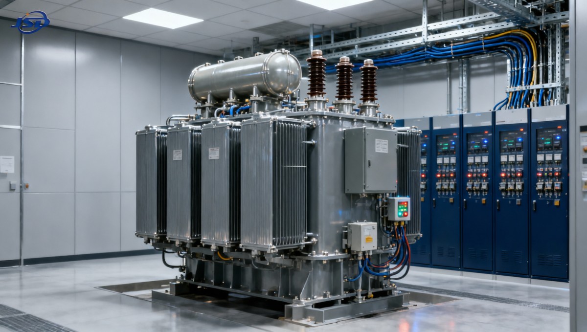
For a 35 kV-to-400 V arrangement, capacity selection can span a wide range depending on whether the transformer serves a small technical facility, a modular data hall, or a larger portion of a campus electrical system. Equipment such as the 35kV/0.4kV Oil-Immersed Power Distribution Transformer illustrates the parameters that should be reviewed in this type of application: capacity range, rated voltage and tap positions, winding material, efficiency, impedance, environmental protection, and available insulating-fluid options.
Those specifications are meaningful only when matched to the site design. An NLTC setting, for instance, may be appropriate where the incoming utility voltage is stable within the planned operating range, while a project with a different voltage-regulation strategy may require a different approach. Similarly, an IP-rated enclosure can support outdoor or exposed installation conditions, but it does not remove the need to verify heat dissipation, foundation design, cable routing, and access for operations personnel.
For projects where reduced fire risk or environmental considerations influence the design, the insulating-fluid choice deserves early review. FR3 vegetable oil may be an option in some transformer designs, but the selection should be coordinated with local rules, insurer requirements, installation location, and the facility’s wider fire-protection engineering. Material choice is part of a system decision, not a standalone label of suitability.
Capacity Planning Should Leave Room for Reality
Data center capacity forecasts are often built around planned IT deployment, but the transformer sees the electrical consequences of more than server nameplate power. Cooling systems, power conversion losses, battery charging, pumps, controls, lighting, and other auxiliaries can materially affect the low-voltage demand. The electrical model should use realistic diversity and operating assumptions, while retaining enough margin for the operating states the site has committed to support.
Expansion also raises a sequencing question: should the site install larger transformers at the beginning, or add transformer capacity in modular stages? There is no single correct answer. Early installation can simplify later construction and preserve available space, but may increase idle losses and tie up capital before capacity is used. Modular deployment can match equipment investment to IT rollout, though it requires a credible plan for future switching, protection changes, outage windows, and physical connection points.
A well-chosen distribution transformer for data centers supports continuous service because its rating, thermal design, losses, voltage characteristics, and monitoring provisions reflect the way the facility will actually operate. The transformer should have enough margin to perform through foreseeable events, yet it should not be selected through oversizing alone. The strongest specifications start with the load and resilience model, then turn those operating requirements into measurable electrical and thermal criteria.

Get a Quote
Regardless of whether you require general advice or specific support, we are happy to help you.
Send Us Your Inquiry Today

Jinshida Electric remains committed to contributing to global energy development through professional manufacturing and superior service.