





Control transformers in HVAC systems: how secondary voltage sag triggers false lockout alarms
Control transformers in HVAC systems are often overlooked until they trigger false lockout alarms—sudden, unexplained shutdowns that halt operation and send technicians down costly diagnostic rabbit holes. For operators managing commercial chillers, rooftop units, or industrial air handling systems, these phantom faults rarely stem from control logic failure or sensor drift. Instead, the root cause frequently lies in secondary voltage sag under load—a transient dip in output voltage that falls below the minimum threshold required by contactors, relays, or programmable logic controllers (PLCs) to maintain coil energization. When this occurs, the system interprets the loss of holding voltage as a safety fault and initiates a lockout sequence—even though no actual overtemperature, airflow, or pressure anomaly exists.
The issue is especially prevalent during startup surges, when multiple control circuits activate simultaneously, or under sustained low-ambient conditions where transformer core losses increase and winding impedance shifts. Unlike power transformers designed for steady-state delivery, control transformers operate at lower kVA ratings and tighter voltage regulation tolerances. A unit rated for 24 VAC secondary output may drop to 19–21 VAC under peak load, well below the typical 22–23 VAC minimum needed for reliable relay hold-in. This isn’t a design flaw—it’s an application mismatch. And it’s preventable with proper selection, verification, and load management—not replacement of the entire control panel.
Why Secondary Voltage Sag Triggers False Lockouts
Most HVAC control logic relies on electromagnetic devices—contactors, time-delay relays, and safety cutouts—that require a minimum “pick-up” voltage to energize and a slightly lower “hold-in” voltage to stay closed. While datasheets often list nominal coil ratings (e.g., “24 VAC ±10%”), real-world performance depends on two interdependent factors: transformer regulation and circuit loading.
Transformer regulation refers to how much the secondary voltage drops between no-load and full-load conditions. It’s expressed as a percentage and calculated as:
(Vno-load – Vfull-load) / Vno-load × 100%
A typical 50 VA, 120 VAC-to-24 VAC control transformer may have 5–8% regulation—meaning its output drops from 24.0 VAC to ~22.2–22.8 VAC at rated load. That’s acceptable. But if the connected load exceeds rating—even momentarily—the sag deepens. Add in aging insulation, elevated ambient temperature (>40°C), or undersized secondary wiring (increasing voltage drop), and output can easily fall to 18–20 VAC. At that point, many standard 24 VAC coils release, breaking the control circuit and triggering a lockout alarm.
Crucially, this behavior is not logged or flagged as a voltage event. The PLC sees only an open input or dropped output signal—and defaults to its programmed safety response. Technicians then spend hours checking refrigerant pressures, airflow switches, and flame sensors before realizing the issue originates upstream, at the transformer.
How to Confirm Voltage Sag Is the Culprit
Diagnosis starts with measurement—not assumption. Use a true-RMS multimeter capable of capturing transient dips (not just average or peak-hold readings) across the secondary terminals while the system cycles through startup and full-load operation.
- Measure voltage at the transformer secondary terminals—not at the far end of control wiring—to isolate transformer performance from line losses.
- Record values during three phases: idle (all loads de-energized), startup (compressor, fans, dampers engaging), and steady-state run.
- Compare results against the minimum hold-in voltage specified for each coil in the system schematic (often 85–90% of nominal, e.g., ≥20.4 VAC for 24 VAC coils).
- If measured voltage falls below that threshold during any phase—and all other components check out—voltage sag is the likely cause.
Note: Don’t rely solely on nameplate ratings. A transformer labeled “24 VAC, 75 VA” may deliver only 62 VA reliably at 40°C ambient due to thermal derating. Always verify actual load in VA: sum the coil VA ratings of all connected devices (not just their current draw), including auxiliary relays, indicator lamps, and interface modules.
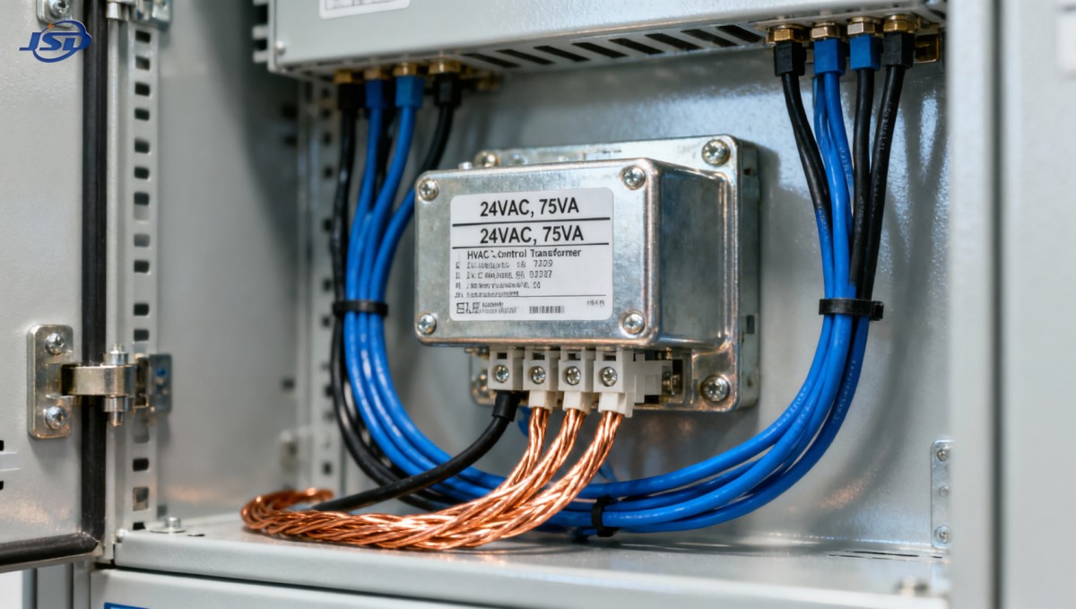
Selecting a Control Transformer That Prevents Sag-Induced Lockouts
Prevention hinges on matching transformer capability to real-world demand—not just nominal load. Key selection criteria include:
- Derated capacity: Choose a unit rated at least 1.5× the total connected VA load, especially in environments above 30°C or with frequent cycling.
- Regulation performance: Look for transformers with ≤4% regulation at full load. High-stability designs use grain-oriented silicon steel cores and optimized winding geometry to minimize impedance rise under load.
- Thermal margin: Units with Class H insulation (180°C) sustain higher ambient temperatures without derating, maintaining consistent output voltage across seasonal extremes.
- Input tolerance: Wide-input-range models (e.g., 100–130 VAC primary) compensate for supply fluctuations that compound secondary sag.
Jinshida’s precision-engineered 1MW/2MWh Liquid Cooling Container Energy Storage System incorporates similar voltage stability principles in its auxiliary power distribution—where uninterrupted 24 VDC control power is critical for BMS communication and thermal management sequencing. That same engineering rigor applies to standalone control transformers: tighter regulation, verified thermal performance, and application-specific derating guidance—not generic catalog specs.
Practical Mitigation Steps (Without Full Replacement)
If upgrading the transformer isn’t immediately feasible, these field adjustments often restore stable operation:
- Load segmentation: Split high-VA loads (e.g., large contactor banks) across separate transformers instead of daisy-chaining them on one secondary.
- Wiring upgrade: Replace undersized secondary conductors (e.g., 18 AWG) with 14 AWG or larger to reduce voltage drop over distance.
- Coil substitution: Where compatible, replace standard 24 VAC coils with wide-range equivalents rated for 18–30 VAC operation—verified for your specific device model.
- Timing adjustment: Introduce staggered startup delays (via PLC or sequencer) to avoid simultaneous inrush currents across multiple control circuits.
None of these fixes address degraded transformer insulation or core saturation—so if measurements show >10% regulation or inconsistent output across repeated tests, replacement is necessary. But in most cases, the issue is sizing and application—not component failure.
When to Suspect Other Causes
Voltage sag isn’t the only source of false lockouts. Rule out these concurrent contributors before concluding the transformer is at fault:
- Ground loops or shared neutrals causing induced noise on control inputs;
- Failing capacitor in the transformer’s internal rectifier (if supplying DC control power);
- Loose or corroded secondary terminal connections increasing resistance and localized voltage drop;
- Harmonic distortion from variable-frequency drives affecting transformer core saturation.
Each requires different test equipment and interpretation—but all share one trait: they’re diagnosable with targeted measurement, not guesswork. If voltage remains stable across all operating conditions yet lockouts persist, shift focus to input signal integrity and logic timing rather than transformer performance.
Stable HVAC operation doesn’t depend on perfect components—it depends on correctly matched components. Control transformers aren’t passive parts; they’re active voltage regulators whose performance directly governs system reliability. Treating them as such—verifying load, measuring under real conditions, and selecting with thermal and regulation margins—eliminates most false lockouts before they disrupt production, comfort, or service calls.

Get a Quote
Regardless of whether you require general advice or specific support, we are happy to help you.
Send Us Your Inquiry Today

Jinshida Electric remains committed to contributing to global energy development through professional manufacturing and superior service.