





24V low voltage transformers for PLC control panels: why inrush current peaks exceed 12× rated current
When selecting a 24V low voltage transformer for PLC control panels, engineers and operators often overlook a critical hidden risk: inrush current spikes can surge over 12× the rated current at power-on—potentially tripping breakers, damaging contactors, or degrading relay life. This isn’t theoretical—it’s a real-world challenge rooted in core saturation and magnetizing surge dynamics.
The phenomenon arises from the transformer’s magnetic circuit behavior during energization. At the instant of switching on, the residual flux in the core and the point on the AC voltage waveform where closure occurs determine whether the core enters deep saturation. If voltage is applied near voltage zero crossing—and the residual flux aligns constructively with the initial half-cycle—the resulting flux demand may exceed the core’s saturation limit by up to 2× its normal peak value. Since magnetizing current rises nonlinearly beyond saturation, even brief excursions into this region draw disproportionately high current—often exceeding 12 times the transformer’s full-load rated current for durations ranging from 0.5 to 6 cycles (10–120 ms), depending on system impedance and core material.
Standard 24V low voltage transformers designed for general-purpose applications rarely account for this transient stress. Their laminated silicon steel cores, while efficient under steady-state operation, exhibit relatively high remanence and low coercivity—making them prone to flux trapping after de-energization. Without intentional mitigation, repeated inrush events accelerate insulation aging in secondary windings and induce mechanical stress in primary winding terminations due to Lorentz forces. In PLC panels, where multiple small transformers may share a common upstream breaker or fuse, cumulative inrush can trigger nuisance trips—even when individual loads remain well within thermal limits.
Core geometry and material selection directly influence inrush magnitude. Grain-oriented electrical steel reduces hysteresis loss but increases remanence, worsening worst-case inrush if not paired with controlled energization timing. Amorphous metal cores offer lower saturation flux density but higher resistivity—reducing eddy current losses and enabling faster flux decay between cycles. However, their brittleness demands precise winding tension control during manufacturing; improper handling introduces micro-cracks that degrade long-term flux stability and increase scatter in inrush behavior across units.
Winding configuration also plays a decisive role. A transformer with high primary leakage inductance—often unintentionally introduced by loose layer-to-layer spacing or non-uniform interleaving—can limit peak inrush by increasing impedance during the initial transient. Yet excessive leakage compromises voltage regulation under load and raises temperature rise during continuous operation. The optimal balance lies not in maximizing or minimizing leakage, but in designing it to intersect with the system’s source impedance such that the time constant of the inrush decay matches the protective device’s short-time pickup threshold. For example, a 24V low voltage transformer feeding a panel with Type B miniature circuit breakers (trip threshold ~3–5× In) benefits from slightly elevated leakage—whereas one connected downstream of a fast-acting semiconductor fuse requires tighter coupling to avoid false triggering.
Thermal mass matters more than often assumed. Small 24V low voltage transformers used in compact PLC enclosures frequently operate near ambient temperature limits. Repeated inrush events deposit energy not only in copper losses but—more critically—in localized eddy current hotspots within the core’s outer laminations. Over time, this contributes to interlaminar insulation degradation and progressive increase in no-load current, further amplifying subsequent inrush peaks. Units with aluminum windings, while lighter and cheaper, exhibit higher resistivity than copper at operating temperature—leading to greater I²R heating during transients and accelerated thermal cycling fatigue at solder joints.
Design-level mitigation strategies fall into three categories: passive, semi-active, and active. Passive approaches include pre-magnetization circuits using resistor-capacitor networks to bias the core before main contactor closure. These are cost-effective but require careful tuning per unit rating and introduce additional failure points. Semi-active methods integrate zero-crossing solid-state relays that delay energization until voltage phase aligns favorably—though they add complexity and must withstand repeated surge currents without derating. Active solutions—such as closed-loop flux sensing combined with controlled DC bias injection—are rare in 24V low voltage transformers due to cost and size constraints, yet represent the most predictable suppression method where reliability justifies investment.
Field validation reveals that inrush behavior varies significantly with installation conditions. Transformers mounted directly on steel cabinet walls experience altered magnetic shunting paths compared to those suspended on insulating brackets—changing both saturation thresholds and flux decay rates. Ambient temperature gradients across the core stack—common in unventilated panels—induce thermal asymmetry in permeability, skewing the symmetry of positive/negative half-cycle inrush peaks. Even cable routing matters: parallel runs of primary supply and secondary control wiring introduce mutual inductance that can either dampen or resonate with the inrush transient, depending on conductor twist rate and separation distance.
Standards provide limited guidance. IEC 61558-2-1 specifies thermal and dielectric tests but does not mandate inrush measurement protocols for safety isolating transformers. UL 5085-1 references short-circuit withstand capability but treats inrush as an application-specific consideration rather than a design parameter. As a result, manufacturers typically characterize inrush only under ideal lab conditions—room temperature, clean sine wave, no residual flux—which rarely reflect field service. Real-world testing should include cold-start (–25°C), hot-start (70°C), and residual flux conditioning via prior de-energization at peak current—procedures often omitted from datasheets but essential for PLC panel integration.
In broader system context, the same principles governing 24V low voltage transformer inrush apply—albeit at different scales—to larger distribution assets. For instance, the 20kV/0.4kV Oil-Immersed Power Distribution Transformer employs FR3 vegetable oil for enhanced thermal stability and reduced oxidation under repeated transient loading, supporting reliable operation during grid re-energization sequences where coordinated inrush management across substations is critical. Its IP65 enclosure and 25-year design life reflect engineering choices prioritizing resilience against environmental and operational stress—not just steady-state efficiency.
Ultimately, specifying a 24V low voltage transformer for PLC control panels requires looking beyond nameplate voltage and VA rating. Engineers must assess core material grade (e.g., M6 vs. M4 steel), verify winding construction details (tightness, interleaving, lead length), request inrush test reports conducted under representative thermal and residual flux conditions, and coordinate protection device coordination curves—not just trip settings—with measured peak duration and decay profile. Ignoring these factors invites intermittent failures that mimic software faults or sensor drift, delaying root-cause analysis and increasing lifecycle maintenance burden.
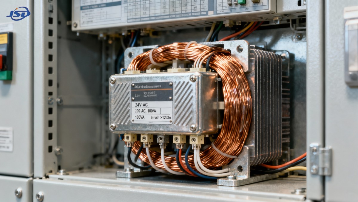
There is no universal “safe” inrush multiplier. A value of 12× reflects a statistically observed worst case under specific alignment conditions—not a guaranteed maximum. Actual peaks depend on the intersection of transformer design, supply network strength, switching device timing, and ambient state. Treating inrush as a fixed parameter invites overspecification or dangerous underestimation. Instead, treat it as a boundary condition shaped by controllable variables—and design accordingly.

Get a Quote
Regardless of whether you require general advice or specific support, we are happy to help you.
Send Us Your Inquiry Today

Jinshida Electric remains committed to contributing to global energy development through professional manufacturing and superior service.