





Outdoor potential transformers: why creepage distance must exceed 25mm/kV in polluted industrial zones
2026.09.24
Jinshida
Creepage distance is not a design margin—it is the primary physical barrier against flashover in outdoor potential transformers operating in polluted industrial zones. For technical evaluators, the 25 mm/kV threshold is not arbitrary; it reflects the minimum surface insulation path required to sustain voltage stress under combined contamination, moisture, and electrical loading. Below this value, field experience shows a sharp, non-linear increase in failure probability—not just during heavy rain or fog, but also during dry-band arcing cycles that initiate long before visible tracking appears.
IEC 60071-1 and GB/T 16927.1 define creepage distance as the shortest path along the insulating surface between two conductive parts. But compliance with these standards does not guarantee performance when pollution severity exceeds Class III (as defined in IEC 60815-1). Industrial environments—especially near steel mills, chemical plants, cement kilns, or coastal refineries—regularly deposit conductive salts, metal oxides, and hygroscopic dusts. These contaminants dissolve in dew or light rain, forming a semi-conductive film. Voltage then concentrates across drying zones, leading to localized heating, carbonization, and eventual flashover—even at nominal system voltage.
The 25 mm/kV requirement emerges from decades of statistical analysis of service failures and accelerated pollution tests. It corresponds to the lower bound where the probability of withstand drops below 90% under standardized salt-fog testing (IEC 60507) for systems up to 36 kV. Above 36 kV, the linear scaling continues, but the margin becomes more critical: at 145 kV, a 25 mm/kV creepage implies 3,625 mm total path length—yet many legacy designs stop at 3,200 mm, accepting higher risk without quantifying it.
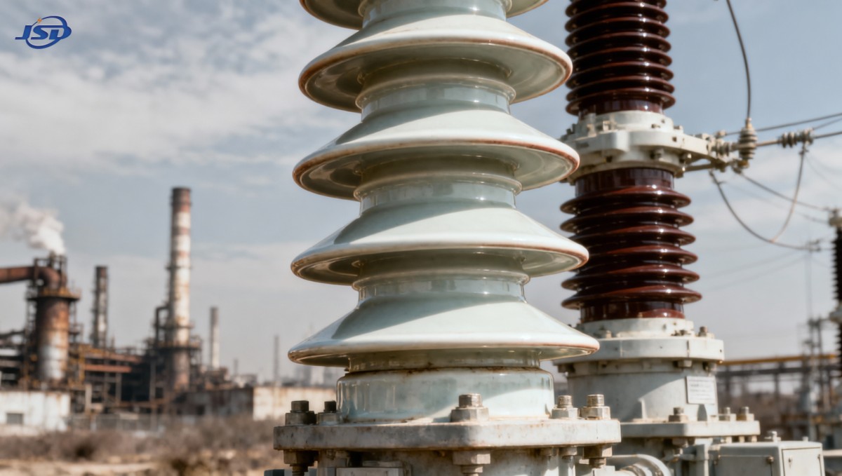
 Geometry matters more than raw length. A straight-line creepage path offers little resistance to surface discharge if it lacks directional complexity. Jinshida Electric’s outdoor potential transformers use multi-ribbed porcelain and silicone rubber housings with alternating shed profiles—designed not just to extend path length, but to interrupt wetting continuity and promote self-cleaning during wind-driven rain. Each shed edge is chamfered to reduce electric field enhancement, and the spacing between sheds is optimized to prevent bridging under heavy contamination while maintaining mechanical rigidity. This geometry-driven approach means that two transformers with identical nominal creepage distances may differ by over 40% in actual withstand voltage under identical pollution conditions.
Material selection is equally decisive. Porcelain remains common, but its hydrophilic surface retains moisture longer and supports more stable conductive films. Silicone rubber, by contrast, exhibits hydrophobicity transfer—the ability to migrate low-molecular-weight polymer chains to the surface, repelling water and suppressing leakage current. However, hydrophobicity degrades under UV exposure and electrical stress. Jinshida’s formulations incorporate alumina trihydrate (ATH) fillers and controlled polymer cross-linking to delay hydrophobicity loss beyond 15 years in tropical industrial zones—verified through 5,000-hour UV + salt-fog cycling per IEC 62217.
Testing protocols must mirror real-world stress sequences—not just steady-state pollution. Flashover rarely occurs during uniform wetting. It happens during the transition: as dew evaporates, or after light rain stops, when partial drying creates high-resistance zones adjacent to conductive paths. Jinshida subjects all outdoor potential transformers to stepwise voltage application under dynamic pollution conditions—applying AC voltage ramping while controlling humidity, temperature, and contamination density in real time. This reveals weaknesses missed by standard 60-second wet-withstand tests.
Misapplication remains widespread. Some engineers assume that indoor-rated units can be deployed outdoors with minor derating—or that a higher system voltage class automatically ensures adequate creepage. Neither holds. A 35 kV transformer rated for indoor use may have only 18 mm/kV creepage; applying it in a Class IV pollution zone (e.g., near a fertilizer plant) increases flashover likelihood by over 7× compared to a 25 mm/kV unit—even if both meet their respective IEC 60071 dielectric strength requirements.
Another misconception treats creepage as independent of grounding configuration. In effectively grounded systems (where neutral is solidly earthed), phase-to-ground voltage stress governs creepage design. But in impedance-grounded or ungrounded systems—common in mining or offshore platforms—the transient overvoltage during single-phase faults can impose 1.73× phase-to-ground voltage across the same insulation. Creepage must then be evaluated against the maximum expected temporary overvoltage (TOV), not nominal voltage alone.
Maintenance assumptions also distort risk assessment. Many procurement specifications require “low-maintenance” units—but no outdoor insulation is maintenance-free. Creepage adequacy assumes periodic cleaning intervals aligned with local pollution accumulation rates. In high-dust environments, annual washing may suffice; near chlor-alkali plants, quarterly inspection and cleaning may be necessary. Jinshida provides contamination rate maps calibrated to regional industrial activity—enabling technical evaluators to estimate realistic cleaning cycles and adjust creepage margins accordingly.
System-level consequences justify conservative design. A flashover on a potential transformer rarely causes only localized damage. Because PTs feed protection relays, metering, and synchro-check circuits, their failure can trigger false tripping, loss of synchronization, or undetected ground faults—leading to cascading outages. In one documented case at a petrochemical complex, repeated PT flashovers during monsoon season caused three unscheduled 220 kV line trips within six weeks—not due to relay malfunction, but because contaminated PT secondaries introduced phase-angle errors exceeding 5°, misleading distance protection algorithms.
This is why Jinshida’s outdoor potential transformers are engineered to exceed 25 mm/kV—not by minimal increments, but with deliberate margin: 28–32 mm/kV depending on system voltage and specified pollution class. That margin accommodates material aging, minor manufacturing tolerances, and unexpected contamination spikes—without requiring recalibration of protection settings or redesign of secondary circuits.
For applications demanding portable, off-grid power resilience—such as emergency substations or rapid-deployment grid support—integrated energy solutions must coexist with robust measurement infrastructure. The 50kW/100kWh Portable Trailer Energy Storage System exemplifies how distributed assets rely on accurate voltage sensing; compromised PT performance directly undermines state-of-charge estimation, islanding detection, and grid-forming stability. There is no redundancy in measurement integrity—only layered assurance.
Ultimately, creepage distance is not a number to be ticked off a checklist. It is the outcome of a chain of interdependent decisions: pollution classification, housing geometry, material chemistry, test methodology, and system grounding. Technical evaluators who treat it as a standalone parameter miss the physics—and pay for it in reliability, safety, and unplanned downtime.

Get a Quote
Regardless of whether you require general advice or specific support, we are happy to help you.
Send Us Your Inquiry Today

Jinshida Electric remains committed to contributing to global energy development through professional manufacturing and superior service.