





Can isolation rectifier transformer prevent ground loop interference in electroplating systems?
Yes — an isolation rectifier transformer can effectively prevent ground loop interference in electroplating systems, but only when properly specified, installed, and integrated into the full power chain. It’s not a universal “plug-and-play” fix. Its effectiveness depends on how well it addresses the root cause: unintended current flow through shared grounding paths between rectifiers, control circuits, instrumentation, and the plating tank itself.
Why Ground Loops Happen — and Why Rectifiers Are Especially Vulnerable
In electroplating, DC power is non-negotiable. But most facilities supply AC from the grid, so rectifiers convert that AC to low-voltage, high-current DC. That conversion stage is where trouble begins. Rectifiers draw large, non-sinusoidal currents rich in harmonics. When multiple devices — like PLCs, pH meters, ammeters, and even auxiliary pumps — share a common ground reference (often via building steel or conduit), small voltage differences across grounding conductors create circulating currents. These currents induce noise in sensitive analog signals and disrupt digital communication — leading to erratic ammeter readings, unstable current regulation, inconsistent coating thickness, and unexpected shutdowns. Crucially, this isn’t just about “noise.” It’s about galvanic coupling: a direct metallic path allowing current to flow where it shouldn’t. Standard step-down transformers with primary-to-secondary winding connections (e.g., Yy0 or Dyn11 without isolation design) do not break this path — they merely transform voltage. Only a true isolation rectifier transformer — engineered with reinforced insulation, electrostatic shielding, and physically separated windings — eliminates the galvanic link while still delivering precise, stabilized AC input to the rectifier.What Makes an Isolation Rectifier Transformer Different?
Not every transformer labeled “isolation” qualifies for electroplating duty. Here’s what matters on the shop floor:- True Galvanic Isolation: Minimum 5 kV dielectric strength between primary and secondary windings, verified per IEC 60076-11. This prevents leakage current from bridging circuits — the core requirement for breaking ground loops.
- Electrostatic Shielding: A grounded copper foil or Faraday shield between windings blocks capacitive coupling of high-frequency noise (especially from rectifier switching transients). Without it, even high-voltage isolation may fail against fast-rising harmonic distortion.
- Low Impedance & Tight Voltage Regulation: Electroplating loads are highly dynamic — current demand surges during part entry and drops during rinsing. A transformer with high impedance causes excessive voltage sag, destabilizing rectifier output. Look for ±0.5% regulation under load variation, not just nameplate rating.
- Harmonic Mitigation Design: Standard transformers overheat under 5th, 7th, and 11th harmonics generated by 6-pulse rectifiers. An isolation rectifier transformer must be K-rated (K-13 or higher) or built with derated core and conductor sizing to handle harmonic heating without derating capacity.
These aren’t theoretical specs — they’re failure points observed in real installations. A transformer meeting only basic isolation standards may pass factory tests but still allow microamp-level leakage currents to corrupt 4–20 mA instrument loops. That’s enough to throw off bath chemistry control or trigger false fault alarms.
Installation Isn’t Optional — It’s Part of the Solution
Even the best isolation rectifier transformer fails if grounding practices undermine its purpose. Common mistakes include:- Connecting the transformer secondary neutral to the same ground bus used by control panels and instrumentation — reintroducing the very path you tried to isolate.
- Running primary and secondary cables in the same conduit — inducing noise capacitively, bypassing the transformer’s shielding.
- Using undersized grounding conductors for the isolated secondary system, causing voltage rise during fault conditions and compromising safety.
When It Won’t Help — and What to Check First
An isolation rectifier transformer solves ground loop issues rooted in power supply coupling — but not all interference is caused by ground loops. Before investing, rule out these more common culprits:- Magnetic coupling: High-current busbars running parallel to signal wires induce noise directly — solved by physical separation or twisted-pair/shielded cabling, not transformer isolation.
- Poor rectifier filtering: If the DC output lacks adequate choke-capacitor filtering, ripple feeds back into control circuits. The transformer can’t fix downstream rectifier design flaws.
- Faulty instrumentation grounding: A single sensor with a broken shield or floating ground can inject noise across the entire loop. Verify each device individually before upgrading infrastructure.
If your system exhibits noise only during specific operations (e.g., crane movement or pump startup), suspect magnetic induction or mechanical vibration — not ground loops. Adding an isolation transformer won’t resolve those.
Real-World Reliability Matters More Than Paper Specs
Electroplating environments are harsh: corrosive vapors, high humidity, temperature swings, and constant vibration. A transformer built for office lighting duty won’t survive here. That’s why robust construction — sealed bushings, corrosion-resistant coatings, copper windings (not aluminum), and thermal monitoring — isn’t optional. It’s what separates a short-term bandage from a long-term solution. Jinshida Electric Power Technology Co., Ltd. applies this same reliability-first philosophy across its product lines — whether supporting industrial plating rectifiers or renewable energy integration. For instance, their Transformer for Wind Power Generation shares key design disciplines: outdoor-rated enclosures, copper windings for thermal stability, and compliance with IEC 60076 — traits directly transferable to demanding industrial applications where uptime and safety are non-negotiable.So — Does It Prevent Ground Loop Interference?
Yes — but conditionally. An isolation rectifier transformer is the most direct, effective, and field-proven method to eliminate ground loop interference *originating from the AC-to-DC conversion stage*. It works not by filtering noise after it appears, but by removing the fundamental pathway that allows it to form. However, success requires matching the transformer’s isolation integrity, shielding, and thermal design to your actual load profile — and enforcing strict, separated grounding practices. Skip either step, and you’ll likely see partial improvement at best… or no change at all. For operators facing recurring measurement drift or unexplained rectifier trips, start here: verify your grounding topology, confirm rectifier harmonic content, and audit transformer specifications beyond the label. When applied correctly, an isolation rectifier transformer isn’t just a component — it’s the quiet foundation beneath stable, repeatable plating results.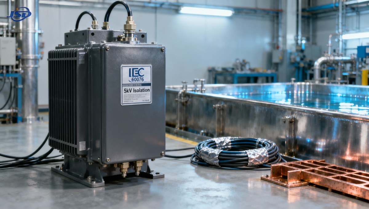

Get a Quote
Regardless of whether you require general advice or specific support, we are happy to help you.
Send Us Your Inquiry Today

Jinshida Electric remains committed to contributing to global energy development through professional manufacturing and superior service.