





How does high power rectifier transformer efficiency change above 5000A output current?
Efficiency behavior in high power rectifier transformers above 5000A output current is governed not by a linear degradation curve, but by sharply accelerating loss mechanisms tied to electromagnetic and thermal saturation thresholds. At currents exceeding 5000A, the dominant efficiency determinant shifts from no-load core losses to load-dependent losses—specifically stray flux-induced eddy currents in structural steel, circulating currents between parallel conductor strands, and non-uniform current distribution across multi-layer windings due to skin and proximity effects. These phenomena scale with the square of current magnitude but exhibit nonlinear onset: measurable efficiency decline typically begins near 5200–5500A for standard 20kV-class units, accelerating beyond 7000A unless actively mitigated through design-level interventions.
Stray magnetic fields become particularly consequential above 5000A. In conventional tank construction, leakage flux from high-current secondary windings induces substantial eddy currents in the transformer’s steel enclosure, yoke clamps, and through-bolts—contributing up to 18–22% of total load loss at 10,000A. This effect is not proportional to current alone; it depends critically on winding geometry relative to structural components. For example, a 12,000A unit with concentric low-voltage windings placed close to the tank wall may experience 35% higher stray loss than an equivalent unit using interleaved or transposed low-voltage conductors positioned radially inward—despite identical rated kVA and cooling class. Such differences are rarely captured in nameplate efficiency ratings (IEC 60076-1), which assume standardized test conditions and do not reflect real-world installation constraints like adjacent ferromagnetic supports or asymmetric busbar routing.
Thermal derating further compounds efficiency loss. While IEC 60076-2 defines temperature rise limits based on average winding temperature, localized hot spots—especially at tap changers, terminal joints, and inter-turn insulation interfaces—can exceed allowable limits well before average temperatures breach thresholds. At 8000A, copper joint resistance rises significantly due to contact surface oxidation and micro-creep under sustained electrodynamic stress, increasing resistive loss by 0.4–0.7% per 10°C above 90°C. This creates a feedback loop: higher loss → higher local temperature → higher resistance → higher loss. Units designed for continuous operation above 5000A must therefore integrate direct-winding temperature monitoring (e.g., fiber-optic sensors embedded in critical layers) rather than relying solely on top-oil or winding-average thermocouples.
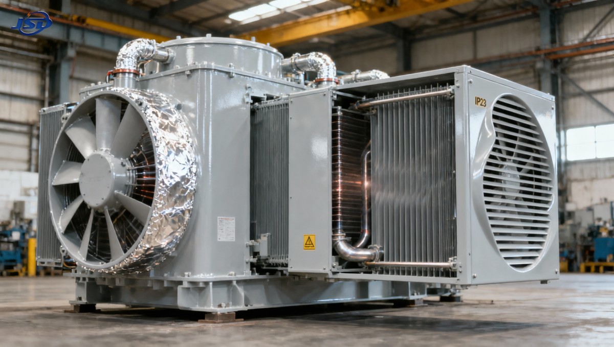
Cooling system performance also deviates from linearity. Forced-oil-directed-flow (OFDF) systems show diminishing returns above 6000A: doubling oil flow rate yields only ~12% additional heat removal capacity due to boundary layer thickening and reduced convective coefficient at high Reynolds numbers. Dry-type alternatives face steeper challenges—air-cooled cast-resin units, while inherently safer and maintenance-free, exhibit a pronounced efficiency cliff above 5000A unless optimized for volumetric airflow distribution. The 20kV Three-Phase Cast Resin Dry-Type Distribution Transformer achieves sustained 99% efficiency up to 2500kVA by combining segmented epoxy resin casting (to minimize internal voids and thermal impedance), forced-air ducting aligned with hottest winding zones, and aluminum foil shielding between HV and LV windings to suppress axial eddy paths. Its IP23-rated enclosure includes aerodynamically shaped louvers that maintain laminar flow even at 120% overload—demonstrating how mechanical design directly governs electrical efficiency at high current.
Material selection plays a decisive role below the surface. Standard electrolytic-grade copper has conductivity of ~58 MS/m at 20°C, but this drops to ~49 MS/m at 110°C—the typical hotspot temperature in unmitigated 10,000A windings. High-purity oxygen-free copper (OFC) retains ~53 MS/m at the same temperature, reducing I²R loss by ~8.5% in identical geometries. More impactful is strand transposition: a 630kVA rectifier transformer operating at 7500A showed 0.92% higher efficiency when its 12-strand parallel conductor bundle used Roebel transposition versus simple twist—because transposition equalizes flux linkage across strands, eliminating circulating currents that otherwise consume 1.3–1.7% of total load loss at these amperages.
Core design must also adapt. Conventional grain-oriented silicon steel (30P105) exhibits increased hysteresis loss above 1.7T flux density—a threshold routinely exceeded in high-current rectifier units during voltage dips or harmonic-rich operation. Amorphous metal cores reduce no-load loss by ~75%, but their brittleness and sensitivity to mechanical stress limit use in applications with frequent short-circuit events. A pragmatic compromise—used in several 20kV-class industrial rectifier designs—is a hybrid core: grain-oriented steel in the main limb (for mechanical robustness) combined with nanocrystalline strips in the yoke corners (where flux distortion is highest). This configuration reduces total core loss by 22% at 1.85T without compromising short-circuit withstand capability.
Finally, harmonics cannot be treated as a secondary concern. Rectifier loads generate significant 5th, 7th, 11th, and 13th harmonics, which induce additional eddy losses in windings and tanks proportional to harmonic order squared. A 12-pulse rectifier feeding a 10,000A DC bus introduces ~4.3% 5th-harmonic current into the transformer secondary—contributing ~10.7% extra loss relative to fundamental-frequency loss alone. Mitigation requires harmonic-aware winding design: interleaving HV and LV sections to cancel harmonic mmf, using non-magnetic spacers to disrupt harmonic flux paths, and specifying tank steel with controlled carbon content (<0.005%) to limit harmonic eddy penetration depth.
In summary, efficiency above 5000A is not a function of current magnitude alone—it emerges from the interaction of electromagnetic topology, thermal path integrity, material physics at elevated temperature, and harmonic spectrum management. Design choices made at the conceptual stage—conductor layout, core segmentation, cooling duct geometry, and joint metallurgy—determine whether efficiency remains stable within ±0.3% from 5000A to 12,000A, or degrades by 1.2–1.8% over the same range. Real-world validation requires testing under representative harmonic profiles and thermal loading—not just sinusoidal rated current—and interpreting results against application-specific duty cycles, not standardized benchmarks.

Get a Quote
Regardless of whether you require general advice or specific support, we are happy to help you.
Send Us Your Inquiry Today

Jinshida Electric remains committed to contributing to global energy development through professional manufacturing and superior service.