





Key Voltage and Impedance Ratings for a Solar Farm Distribution Transformer
Selecting a distribution transformer for solar farms is not simply a matter of matching transformer kVA to inverter MW. Voltage ratio and impedance determine how the transformer behaves during normal export, reactive-power operation, grid disturbances, energization, and faults. A unit that appears correct on a single-line diagram can still create poor voltage control, excessive fault duty, nuisance protection trips, or insulation stress if these ratings are not coordinated with the collector system and point of interconnection.
For technical evaluation, start with the electrical system around the transformer: inverter output voltage, collector feeder voltage, utility interconnection voltage, grounding method, cable lengths, fault level, protection philosophy, and expected operating range. The transformer should be evaluated as part of that system, not as an isolated item of equipment.
Voltage Ratings Must Match the Actual Operating Envelope
A solar plant transformer commonly steps inverter output voltage up to a medium-voltage collector circuit, or steps collector voltage up again for grid export. The nameplate voltage ratio must align with the nominal system voltages, but nominal values alone are not enough. The transformer also needs to maintain acceptable secondary voltage while generation, reactive power demand, feeder losses, and grid voltage all change.
The high-voltage rating should be selected for the collector or grid side that the transformer directly serves. The low-voltage rating must match the inverter-side arrangement, including whether several inverter blocks are paralleled at a low-voltage bus before transformation. A mismatch is not always obvious: an inverter may tolerate a broad voltage range, while its ability to deliver full active and reactive power changes near the limits of that range.
Evaluators should distinguish between the rated ratio and the required voltage at the transformer terminals. Long medium-voltage collector runs create voltage drop when power is exported. At light generation, reverse reactive power flow or grid-side voltage variation may move the terminal voltage in the opposite direction. A fixed-ratio transformer that works at peak irradiance may therefore be less suitable during low-output voltage-control periods.
Tap Range Is a System-Control Decision
Off-circuit taps are often sufficient where the grid voltage is stable and the project design has a narrow operating envelope. They allow the transformer ratio to be set during commissioning, but not adjusted while energized. This is useful when the principal purpose is to compensate for a known, predictable difference between design voltage and actual site voltage.
An on-load tap changer may be appropriate where the transformer is intended to participate actively in voltage regulation. That choice must be coordinated with the plant controller, inverter reactive-power capability, protection settings, and the utility operating philosophy. Adding regulated taps without clear control coordination can lead to unnecessary tap operations or competing voltage-control responses between inverters and transformer equipment.
The correct question is not “Does this transformer have taps?” It is “Which device is responsible for voltage control at each point in the plant, and under which operating conditions?”
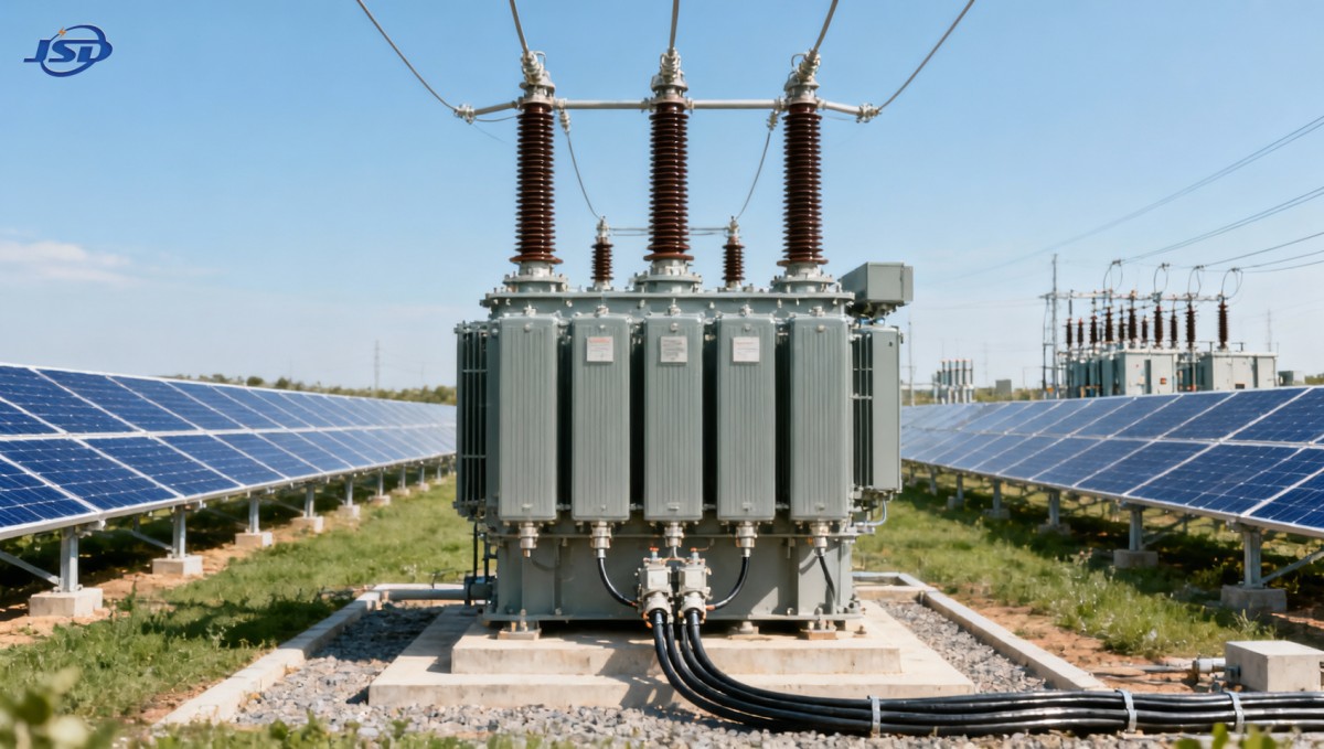
Insulation Coordination Is More Than the Nominal kV Rating
The nominal voltage tells only part of the insulation story. A transformer connected to an overhead collector line, a cable network, or a utility substation may see different transient conditions. Lightning exposure, switching events, cable capacitance, and the arrangement of surge arresters all affect the stress applied to transformer terminals.
Insulation coordination should consider the transformer’s specified withstand levels, surge-arrester protective level, lead length between arrester and transformer, cable terminations, and site altitude where relevant. Long connections between a surge arrester and a transformer can reduce the practical protection seen at the transformer terminals during steep-front transients. This is particularly relevant in outdoor solar sites where equipment is distributed over a large area.
Connection type also matters. A delta winding can block zero-sequence current transfer between systems and provide a path for certain harmonic components. A grounded-wye winding establishes a neutral reference and supports a particular grounding and protection approach. Neither connection is universally preferable. The choice must follow the utility grounding requirements, collector-system design, inverter transformer arrangement, and fault-protection study.
Transformer Impedance Controls Several Outcomes at Once
Percent impedance is the transformer’s internal voltage drop at rated current, expressed as a percentage of rated voltage. It is often treated as a simple fault-current value, but it affects normal voltage regulation, short-circuit duty, transformer paralleling, and the response of protection equipment.
Higher impedance generally limits the current available from the transformer during a downstream fault. This can reduce the interrupting duty imposed on switchgear and help contain fault contribution where available fault levels are high. The trade-off is greater voltage drop as load current rises. In a solar facility, that drop may reduce the voltage available to inverters during high export or reactive-power support, depending on which side of the transformer the inverter is connected to and how the plant is controlled.
Lower impedance reduces the transformer’s own voltage drop and can improve voltage stiffness at the connected bus. It also allows higher fault current. That may require equipment with greater short-circuit capability and may change the coordination margins for feeder relays, fuses, and breaker settings.
The required value should come from a load-flow study and a short-circuit study, followed by a protection review. Selecting an impedance value only because it is common for a particular kVA range is a weak basis for a solar project. Collector cable impedance, utility source strength, inverter fault-current behavior, and parallel transformer paths can shift the result materially.
Do Not Apply Utility-Source Assumptions to Inverter Fault Current
Traditional transformer calculations often assume a strong rotating-machine source behind the transformer. Solar inverters do not behave in the same way. Their fault current is controlled electronically and is typically limited by inverter controls and grid-code behavior. That does not make transformer impedance unimportant; it means the fault study must model the actual generation source correctly.
For example, a lower transformer impedance may not create the same increase in fault current that it would with a large conventional generator, yet it can still affect voltage recovery, relay sensitivity, and contribution from the utility side. Protection settings should therefore use the inverter manufacturer’s fault-current and control-response data rather than generic source assumptions.
Impedance Tolerance and Parallel Operation Need Attention
Where multiple block transformers operate on a common collector bus, or where transformers may be paralleled during maintenance and contingency operation, impedance consistency becomes important. Units with materially different impedance values do not share load evenly. The lower-impedance unit tends to carry more current, which can cause unequal loading even when nameplate capacities are similar.
Voltage ratio, tap position, vector group, phase displacement, and impedance must all be compatible for intended parallel operation. A project may not plan to parallel units routinely, but temporary switching configurations are common enough that this should be resolved in the electrical design rather than discovered during outage work.
Manufacturing tolerance also matters. The procurement specification should state the required impedance at the defined rated condition and identify the permitted tolerance. This gives the project team a basis for checking test documentation and confirming compatibility before energization.
Losses and Temperature Rise Affect Rating Decisions
Solar generation has a variable load profile, but the transformer is still exposed to daily thermal cycling, elevated ambient temperature, solar radiation, dust, and limited airflow in many installations. No-load loss is present whenever the transformer is energized, including low-generation periods. Load loss increases with current and becomes especially relevant during sustained high-output operation or when reactive power is requested at the same time as active power export.
Do not assume that a larger transformer automatically provides a better operating margin. Oversizing can reduce load-related heating, but it may increase no-load losses and capital cost. The more useful approach is to define the expected active-power output, reactive-power obligations, ambient conditions, cooling arrangement, allowable overload profile, and future expansion requirement. Those inputs determine whether the proposed kVA rating and loss evaluation are appropriate.
For special auxiliary loads such as battery systems, water treatment, tracking drives, or power-electronic equipment, isolation and waveform considerations may require a separate transformer instead of sharing the main solar block transformer. Where a dedicated rectifier-duty unit is needed, an Isolation and Rectifier Special Transformer can be evaluated for its specified voltage arrangement, winding connection, cooling method, and IEC 60076 alignment. It should not be substituted for the main solar distribution transformer unless its duty, insulation design, impedance, and grid connection requirements have been engineered for that role.
A Practical Rating Review Before Purchase
A sound specification converts system-study results into clear transformer requirements. Before releasing a purchase order, confirm the following points:
- Rated primary and secondary voltages, frequency, phase arrangement, and the required voltage range at transformer terminals.
- Tap type, tap range, tap position, and which controller has authority over plant voltage regulation.
- Specified impedance and tolerance, checked against load flow, fault duty, and protection sensitivity.
- Vector group, neutral arrangement, grounding method, and zero-sequence behavior required by the collector and grid systems.
- Insulation levels and surge-protection arrangement suited to the actual line, cable, and substation configuration.
- Rated capacity under the intended cooling mode, with ambient conditions and reactive-power duty included in the thermal assessment.
- No-load and load-loss requirements, along with the test information needed to verify them.
- Outdoor enclosure, corrosion environment, clearances, cable entry, monitoring interfaces, and maintenance access.
Jinshida Electric Power Technology Co., Ltd. supports transmission and distribution applications with engineering, manufacturing, and quality-control processes focused on stable operation in grid, industrial, new-energy, and infrastructure environments. For a solar transformer inquiry, the most useful technical package is not merely a nameplate rating request. It is the single-line diagram, inverter data, collector voltage, grounding scheme, grid-interface requirements, short-circuit study inputs, and site operating conditions.
Where Evaluations Commonly Go Wrong
One frequent error is specifying the voltage ratio from the one-line diagram while ignoring voltage drop across the collector circuit. Another is selecting a low impedance to improve regulation without checking switchgear duty and protection coordination. The opposite error also occurs: choosing high impedance to limit faults, then finding that voltage drop constrains inverter reactive-power performance at the point where support is required.
It is also risky to treat vector group as a standard catalogue choice. The winding connection influences grounding, fault behavior, harmonic paths, and how the solar plant interacts with the utility system. A familiar connection may still be unsuitable for the protection scheme or interconnection requirement.
The best specification process begins with the network model, not the transformer catalogue. Once voltage range, fault behavior, grounding, protection, and thermal duty are defined, the voltage ratio and impedance can be selected for the plant’s actual operating conditions rather than for a generic transformer application.

Get a Quote
Regardless of whether you require general advice or specific support, we are happy to help you.
Send Us Your Inquiry Today

Jinshida Electric remains committed to contributing to global energy development through professional manufacturing and superior service.