





Three-Phase Electrical Substation Transformers: Core Specification Basics
Three-Phase Electrical Substation Transformers: Core Specification Basics
A three phase electrical substation transformer is one of the quiet essentials behind a functioning power network. It may sit inside a compact urban substation, beside a factory production line, at the edge of a solar facility, or within a public infrastructure project. Regardless of location, its job is fundamental: convert electrical energy between voltage levels while preserving the stability, safety, and quality of supply required by connected equipment.
For someone beginning the research process, transformer specifications can appear dense: kVA ratings, vector groups, impedance percentages, insulation classes, tap ranges, losses, and cooling codes often arrive in the same datasheet. Yet these items are not merely technical labels. Together, they describe whether a transformer fits the network, handles the expected load profile, works safely in its installation environment, and remains practical to operate over many years.
This guide explains the core parameters in a practical way, with particular attention to the questions project planners, procurement teams, and facility managers commonly need answered before moving toward a technical selection.
What Makes a Transformer “Three-Phase”?
Three-phase electricity is the standard supply format for most utility-scale, commercial, industrial, and infrastructure systems. Instead of one alternating voltage waveform, it uses three waveforms separated by 120 electrical degrees. This arrangement delivers power more smoothly and efficiently, especially for motors, large loads, and broad distribution networks.
A three-phase transformer is designed to transfer this three-phase power from one voltage level to another. In a substation, it may step high-voltage power down for regional or local distribution, or step voltage up before electricity enters a transmission network. At the distribution end, a transformer may reduce medium voltage—such as 20 kV—to a low-voltage supply suitable for buildings, machinery, lighting, charging systems, or local feeder circuits.
The term does not describe one single product format. A three phase electrical substation transformer may be oil-immersed or dry-type, installed outdoors or indoors, designed for a utility substation or dedicated to a customer facility. The correct choice begins with understanding the duty it will perform rather than choosing only by rated capacity.
Start with the Electrical “Address”: Rated Voltage and Voltage Ratio
The first essential specification is the transformer’s rated voltage. This identifies the nominal voltage of the high-voltage (HV) and low-voltage (LV) windings. A 20 kV/0.4 kV transformer, for example, is intended to receive power from a 20 kV medium-voltage system and deliver power at 400 V on the low-voltage side.
Voltage selection must align with the actual network, not just a familiar market convention. Distribution systems vary by country, utility, industrial site, and project type. Common LV values include 0.4 kV and 0.415 kV, while medium-voltage systems may operate at 10 kV, 11 kV, 20 kV, 22 kV, 33 kV, or other designated levels.
The voltage ratio also has a direct relationship with insulation design. Windings, bushings, terminals, and clearances must be suitable not only for normal operating voltage but also for expected temporary overvoltage and switching or lightning-related surge conditions. This is why buyers should provide the system’s highest voltage and insulation coordination requirements where possible, rather than stating only the nominal voltage.
Why tap settings matter
No power system holds precisely the same voltage at every moment. Load changes, feeder length, upstream regulation, and generation conditions can shift the actual voltage seen at a transformer. Tap changers allow adjustment of the transformation ratio so the secondary voltage remains closer to its intended level.
For a fixed distribution application, an off-circuit tap range such as ±2 × 2.5% on the high-voltage winding is common. These taps are normally set while the transformer is de-energized. Projects needing frequent voltage regulation may require an on-load tap changer, though that is more typical for larger power transformers and grid substations than for conventional dry-type distribution units.
Capacity Is More Than a kVA Number
Transformer capacity is normally stated in kilovolt-amperes (kVA) or megavolt-amperes (MVA). It represents the apparent power the unit can continuously deliver under its specified service conditions. A 1,000 kVA transformer is not automatically the right answer for a site with a calculated 1,000 kVA demand; practical selection requires a look at load behavior, ambient temperature, harmonics, expected expansion, and redundancy strategy.
In everyday planning, a site may have a low average demand but intense peaks caused by motor starts, welding equipment, furnaces, elevators, data processing equipment, EV charging, or rapidly changing renewable-energy loads. Oversizing without analysis can increase upfront cost and no-load losses. Undersizing can create temperature rise, voltage drop, shortened insulation life, and operational limitations during growth.
A useful selection discussion should include:
- Present maximum demand and expected future load growth;
- Load factor: whether the site runs near full load continuously or only at certain hours;
- Power factor and the presence of large reactive loads;
- Nonlinear loads that introduce harmonic currents;
- Required overload capability and its permitted duration;
- Whether one transformer must carry critical loads if another unit is unavailable.
For example, a transformer rated for 50–5,000 kVA may cover a wide range of distribution applications, but the final rating should still be based on the project’s load study. Capacity is a design decision, not simply a catalogue filter.
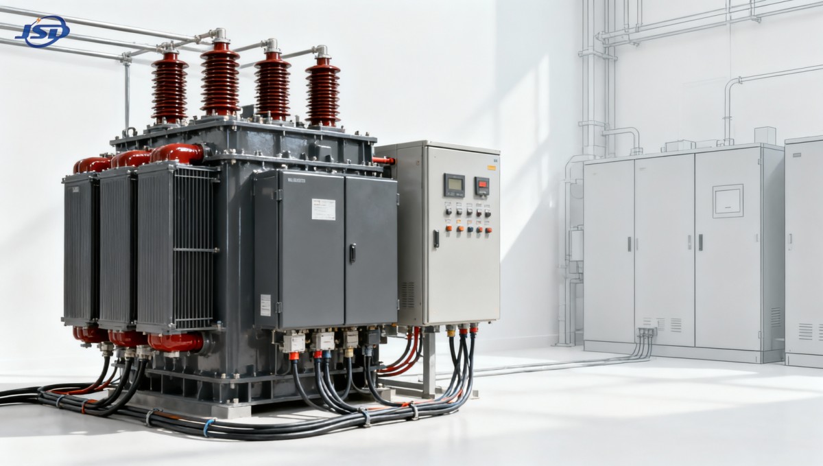
Cooling Method and Insulation: A Key Choice for the Installation Environment
Cooling is central to transformer reliability because heat is one of the main factors affecting insulation aging. The two broad categories are liquid-filled transformers and dry-type transformers. Both have established uses; neither is universally better.
Oil-immersed units use insulating liquid for both cooling and dielectric insulation. They are widely used in outdoor utility and industrial settings and are often selected for large ratings or projects where space, fire-risk controls, and environmental protection measures are appropriately managed.
Dry-type transformers use air and solid insulation systems rather than liquid coolant. Cast resin designs encapsulate the windings in epoxy resin, helping provide resistance to moisture, dust, and many challenging indoor conditions. Because there is no insulating oil, dry-type units are often considered where fire safety and reduced liquid-spill risk are priorities—such as commercial buildings, public facilities, transport sites, hospitals, high-rise developments, and indoor substations.
Cooling codes clarify how the transformer dissipates heat. Natural-air cooling is typically used for normal operation, while forced-air cooling adds fans to increase heat removal when a higher short-term output is required. Any overload capability must be interpreted carefully: it depends on the manufacturer’s thermal design, specified ambient conditions, cooling arrangement, duration, and operational controls. It should never be treated as unlimited spare capacity.
Losses, Efficiency, and the Cost of Operating for Years
Transformer efficiency is usually high, but the losses that remain become meaningful over a long service life. There are two principal categories.
No-load loss, sometimes called core loss, occurs whenever the transformer is energized, even if little or no load is connected. It is associated mainly with the magnetic core. Load loss, often called copper loss, increases as current flows through the windings and associated conductive parts. Load loss rises approximately with the square of the current, which is why high-load operation deserves close attention.
A lower-loss design can reduce energy consumption, but comparison must be fair. Ratings, impedance, winding material, temperature reference, test standards, and accessory requirements can affect quoted values. Instead of reviewing only a single efficiency percentage, ask for guaranteed no-load and load-loss figures at the relevant rating and compare them against the expected annual load profile.
This distinction is particularly important in facilities that remain energized around the clock but operate at low average load. In those cases, no-load loss can have a larger share of the annual energy cost than planners initially expect. Conversely, a heavily utilized manufacturing transformer needs close scrutiny of load loss and thermal performance.
Impedance: The Specification That Influences Fault Levels and Voltage Drop
Percentage impedance is often overlooked by non-specialists, yet it has a major effect on substation behavior. In simple terms, transformer impedance limits the short-circuit current that can flow during a downstream fault. It also affects the voltage drop experienced as load changes.
Lower impedance generally permits higher fault current, which may support motor starting and reduce voltage drop under load. However, it can also raise the interrupting-duty requirement for downstream switchgear and circuit breakers. Higher impedance reduces fault current but may produce more noticeable voltage variation, especially with large fluctuating loads.
There is no universally ideal impedance value. The appropriate level depends on the utility source, cable lengths, motor loads, parallel-transformer arrangements, protection coordination, and switchgear ratings. When a transformer is added to an existing facility, a fault-level study is often more valuable than a quick replacement based on the old nameplate alone.
Vector Group, Earthing, and Phase Relationship
A transformer vector group defines the winding connections—such as delta or star—and the phase displacement between the HV and LV sides. It may look like a compact code, but it affects system compatibility, neutral availability, harmonic behavior, and the feasibility of parallel operation.
A star-connected low-voltage winding with an accessible neutral is common where a three-phase, four-wire supply is needed for mixed power and lighting loads. Delta connections may help manage certain triplen harmonics and provide a path for circulating harmonic currents. The selected arrangement must suit the earthing system and protection philosophy of the network.
Parallel operation deserves special caution. Transformers operating in parallel should have compatible voltage ratios, vector groups, impedance values, tap positions, and phase sequence. A mismatch can cause circulating currents or unequal load sharing, even when nameplate capacities appear similar.
Protection Level, Temperature Monitoring, and Enclosure Requirements
A transformer does not work in isolation. Its safe operation depends on coordinated protection, monitoring, and installation design. For dry-type equipment, temperature sensors and controllers can monitor winding temperatures, trigger alarms, start cooling fans, and initiate trip commands if unsafe conditions are reached.
Ingress protection is another practical issue. An enclosure rated IP23, for example, provides a defined level of protection against access to hazardous parts and certain water exposure, but it is not equivalent to a sealed outdoor cabinet. Dust levels, condensation, corrosive atmospheres, ventilation, altitude, seismic requirements, and room temperature should be evaluated before selecting an enclosure or installation layout.
Fire performance is especially relevant for indoor projects. A flame-retardant classification such as F1 may be specified for dry-type transformer installations where fire behavior is a significant design consideration. Still, transformer selection should be coordinated with the building’s overall fire strategy, ventilation plan, cable routing, clearances, and local code requirements.
A Practical Example: 20 kV Distribution for Modern Facilities
Many industrial, commercial, renewable-energy, and public-facility projects receive medium-voltage power and need a dependable low-voltage distribution point close to the load. In such cases, a cast-resin distribution transformer can be a practical fit where indoor installation, low-maintenance operation, and fire-conscious design are important.
One example is the 20kV Three-Phase Cast Resin Dry-Type Distribution Transformer. This type of unit can be configured for a 20 kV input and 0.4 kV or 0.415 kV output, with capacities covering common distribution ranges. Its high-voltage tapping provision supports adjustment to local supply conditions, while temperature protection and control features support operational visibility. For specified forced-air conditions, some designs may provide temporary operation up to 120% of rated load; the project team should confirm the exact duty cycle and control requirements during technical review.
Such an application is not limited to one sector. Rural grid upgrades, workshops, retail complexes, new-energy balance-of-plant systems, and public infrastructure can all have different priorities. A rural location may focus on voltage variation and service access. A factory may focus on harmonic loads and continuity. A commercial building may prioritize compact indoor placement and fire performance. The transformer must be specified around those realities.
Questions to Ask Before Requesting a Quotation
A clearer technical inquiry usually leads to a more useful proposal and fewer late-stage revisions. Before contacting a manufacturer or supplier, prepare the following information:
- HV and LV nominal voltages, frequency, and earthing arrangement;
- Required capacity, load profile, and future expansion expectations;
- Indoor or outdoor location, ambient temperature range, and altitude;
- Dry-type or liquid-filled preference, including fire and environmental constraints;
- Required impedance, vector group, tap range, and protection accessories;
- Applicable IEC, ANSI/IEEE, utility, or local project standards;
- Space limitations, cable entry direction, enclosure needs, and transport restrictions;
- Testing, documentation, inspection, and commissioning expectations.
Manufacturers with strong engineering and quality-control processes can help turn these site conditions into a workable configuration. For global projects, it is also worth checking how the design will be adapted to local standards, how routine tests are documented, and what technical information will be available for installation and maintenance teams.
The Right Transformer Is a Network Decision
Selecting a three phase electrical substation transformer is ultimately about matching equipment behavior to the electrical system around it. Voltage ratio makes it compatible with the network. Capacity supports the load. Cooling and insulation suit the location. Impedance shapes fault current and voltage performance. Vector group and earthing determine how the transformer interacts with protection and downstream circuits.
When these specifications are considered together, the transformer becomes more than a passive box between two voltage levels. It becomes a stable foundation for safe distribution, efficient operation, and future-ready power planning. That is the level of understanding worth building before a final model, rating, or installation arrangement is approved.

Get a Quote
Regardless of whether you require general advice or specific support, we are happy to help you.
Send Us Your Inquiry Today

Jinshida Electric remains committed to contributing to global energy development through professional manufacturing and superior service.