





Technical Acceptance Tests for Substation Transformers with Tap Changers
Acceptance testing for an electrical substation transformer with tap changer should establish more than whether the unit energizes without an immediate alarm. The test program must demonstrate that the transformer, its tap-changing equipment, protection interfaces, control wiring, and documented ratings agree with the approved design and can be placed into service without creating an avoidable insulation, switching, or operational risk.
For quality and safety teams, the priority is to detect defects while they can still be corrected under controlled conditions. A transformer may pass routine electrical checks yet remain unsuitable for commissioning if its tap changer operates on the wrong phase, its position indication is inconsistent, its interlocks are bypassed, or its selected tap does not match the intended system voltage. Acceptance therefore needs both measured test results and functional evidence.
Start with the approved technical basis
Testing cannot be judged properly without a controlled reference package. Before field work begins, the acceptance team should confirm the transformer nameplate, approved drawings, factory routine test records, tap-changer documentation, protection philosophy, and commissioning procedures. The objective is to prevent a common failure mode: a technically sound test result being accepted against the wrong rating, vector group, tap range, or wiring arrangement.
The review should establish whether the transformer has an off-circuit tap changer or an on-load tap changer (OLTC). These devices serve different operating purposes and require different acceptance depth. An off-circuit tap changer is adjusted only when the transformer is isolated and de-energized. An OLTC is designed to change ratio while energized and normally involves a motor drive, diverter switch, control cabinet, position transmitter, alarms, and interlocking functions. Treating both arrangements as the same equipment can leave major functions untested.
- Confirm rated voltage, rated power, frequency, vector group, impedance, cooling mode, and insulation level against the approved specification.
- Verify the tap range, number of positions, nominal position, and voltage change per step.
- Check that the actual serial number and tap-changer identification match the factory records and site documentation.
- Review whether the protection settings and metering ratios were developed for the installed tap range and vector group.
- Confirm that the selected commissioning tap corresponds to the anticipated incoming voltage and planned operating condition.
A mismatch in this stage should stop the acceptance sequence until the discrepancy is resolved. A test report cannot compensate for an incorrect equipment configuration.
Visual inspection is a technical test, not a paperwork exercise
Visual and mechanical inspection should precede insulation testing and functional energization. It establishes whether shipping damage, installation errors, contamination, loose connections, inaccessible grounding points, or incomplete auxiliary wiring may affect later results. This is particularly important where the transformer has been stored on site, moved after delivery, or installed in a confined substation room.
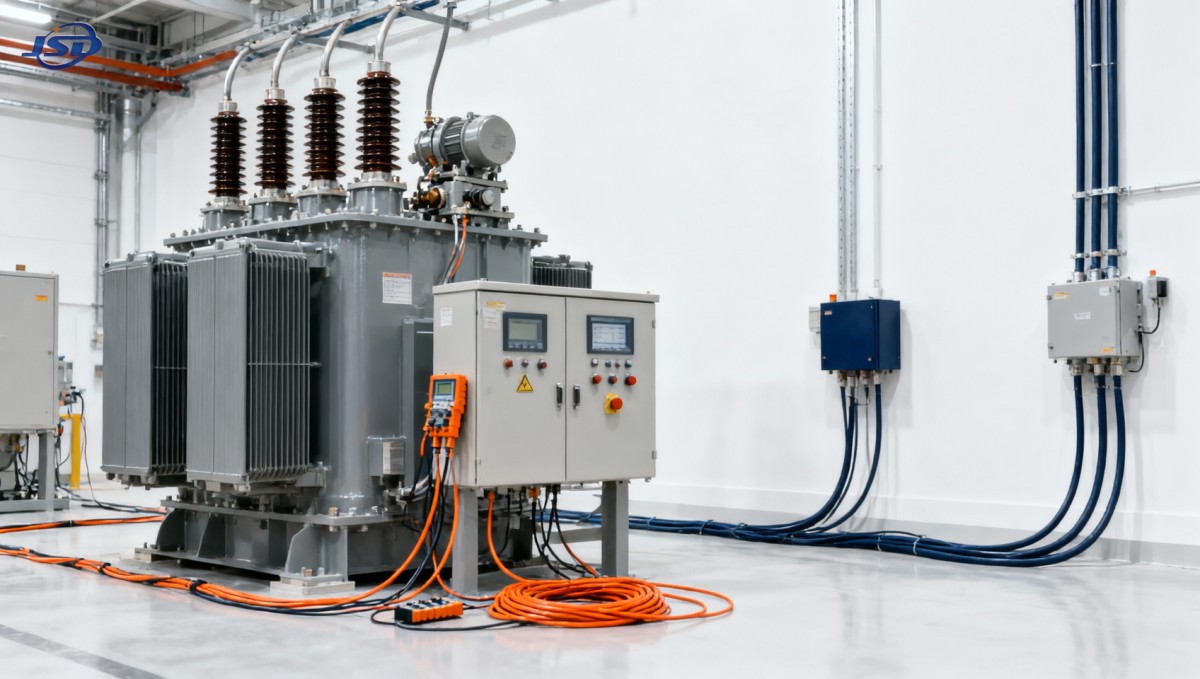
Inspect bushings, terminals, cable boxes, neutral connections, pressure-relief components where applicable, earthing conductors, marshalling boxes, cooling equipment, and external tap-changer mechanisms. The inspection should also confirm that all temporary transport restraints, packing materials, and protective covers have been removed in accordance with the manufacturer’s instructions.
For dry-type transformers, particular attention is needed around cast-resin winding surfaces, ventilation paths, enclosure condition, and temperature-monitoring circuits. A dry-type design removes oil-related acceptance tasks such as dielectric fluid sampling, but it does not reduce the importance of insulation integrity, connection torque, temperature protection, and tap setting verification. For example, a 20kV Three-Phase Cast Resin Dry-Type Distribution Transformer with a high-voltage tap range of plus or minus two 2.5 percent steps should be accepted against the approved tap setting and voltage plan, not simply against its nominal 20 kV rating.
Electrical tests should confirm condition and configuration
Electrical acceptance tests must be selected according to the transformer type, project specification, applicable standard, and manufacturer instructions. The precise test voltages, acceptance values, and test sequence should be defined in the approved commissioning method rather than assumed from a generic checklist. Several tests are commonly used because they expose different categories of error.
Insulation resistance and polarization behavior
Insulation resistance testing between windings and earth provides an initial indication of insulation cleanliness, moisture exposure, damaged leads, or unintended connections. On its own, a high reading is not conclusive evidence of good insulation condition; ambient temperature, humidity, test duration, transformer design, and test equipment all influence the result. Values should be recorded with test conditions and compared with the manufacturer’s guidance, previous records where available, and the project acceptance criteria.
Where the specified procedure requires it, polarization index or time-based insulation resistance readings can provide additional information. A sudden unexplained difference between phases or between comparable tests deserves investigation before any high-energy test or energization is attempted.
Winding resistance
Winding resistance measurement is one of the most valuable tests for a transformer with a tap changer. It can reveal high-resistance joints, loose or damaged leads, poor tap-selector contact, incorrect internal connections, and phase imbalance. Measurements should be made on all phases and at each required tap position, with enough stabilization time for readings to settle.
The acceptance team should look for a logical progression as the tap position changes. The purpose is not merely to produce a set of numbers. A discontinuity, unexpected phase difference, unstable reading, or value inconsistent with the manufacturer’s test record may indicate a contact problem or wiring issue that will become more serious under load.
Turns-ratio, polarity, and vector-group verification
Transformer turns-ratio testing should be performed across the tap range required by the commissioning plan. This confirms that the actual voltage transformation follows the selected tap position and that the tap changer is mechanically and electrically aligned with its indication. Testing should also verify polarity, phase displacement, and vector group where relevant to the installation.
This check has direct system consequences. An incorrect ratio affects secondary voltage. A wrong vector group or incorrect phase connection can create circulating current, protection maloperation, metering errors, or an unsafe parallel operation condition. Where transformers are intended to operate in parallel, acceptance records should explicitly confirm compatible ratio, vector group, impedance assumptions, and tap position.
Excitation current and impedance-related checks
Excitation current testing can help identify abnormal core conditions, winding issues, or connection errors. Results should be interpreted by phase pattern and by comparison with approved factory data, not by a single universal value. Similarly, impedance or short-circuit impedance verification may be required when the specification calls for it, especially when network fault studies, parallel operation, or protection coordination depend on the stated impedance.
These tests are often most useful when viewed together. A ratio test that appears normal does not remove the need to examine winding resistance, and balanced resistance readings do not prove that vector-group connections are correct.
Tap-changer acceptance needs a separate functional record
Tap-changing equipment is frequently the most operationally sensitive part of the transformer acceptance process. The inspection must establish that the position shown locally, remotely, and in control logic reflects the actual electrical position. A correct mechanical movement is insufficient if the supervisory control system receives the wrong indication or the transformer ratio does not change as expected.
For an off-circuit tap changer, the basic requirements are isolation, lockout, correct mechanical engagement, clear position marking, and confirmation through turns-ratio and winding-resistance testing. The test record should state the final locked position. Safety management should ensure that the adjustment procedure prevents operation while energized and that the warning labels are visible after installation.
For an OLTC, acceptance is broader. The functional test should cover the complete operating range under the manufacturer-approved conditions, including local operation, remote operation where provided, raise/lower commands, position indication, end-limit behavior, and stopping at each position. Any abnormal sound, hesitation, incomplete movement, inconsistent indication, or unexplained motor current should be investigated rather than recorded as a minor observation.
- Verify that the tap position at the drive mechanism agrees with the transformer’s electrical ratio test result.
- Confirm local/remote selector logic, control power supply, fuses or protective devices, and terminal identification.
- Test electrical and mechanical end limits without forcing the mechanism against a stop.
- Check alarm, blocking, and interlock functions specified for the control scheme.
- Verify remote indications, supervisory signals, and event points where they are part of the substation control system.
- Confirm that automatic voltage control, if installed, is inhibited or managed appropriately during commissioning tests.
Where oil-immersed OLTC equipment is used, the acceptance scope may also include checks of the associated compartment, oil level indication, leaks, pressure devices, heaters, and filtration or treatment records where applicable. These details should follow the equipment design and approved maintenance instructions rather than being assumed for every transformer.
Protection, alarms, and trip circuits must be proven from end to end
A transformer can be electrically healthy and still present a commissioning risk if its protective functions are incomplete. Acceptance should confirm not only that individual relays or sensors operate, but that the intended alarm, trip, lockout, annunciation, and control responses occur through the installed circuit.
The exact devices depend on the transformer design. Typical interfaces may include winding-temperature indicators, temperature sensors, cooling fan controls, Buchholz or pressure devices on applicable liquid-filled units, sudden-pressure functions, oil temperature devices, and OLTC alarms. Each circuit should be traced from the initiating contact or sensor through terminal blocks, marshalling equipment, protection panels, trip relays, and breaker trip coils as required by the scheme.
For temperature-protected dry-type transformers, test the sensors, controller settings, alarm stages, fan start logic where forced air cooling is installed, and trip output. Where overload capability depends on forced-air operation, the acceptance team should confirm that cooling control is available and that the operating procedure does not treat the higher rating as an unconditional continuous rating.
Documentation determines whether the acceptance result is usable
Acceptance is incomplete when the test values exist only in a commissioning contractor’s worksheet. The final dossier should allow an operator, safety manager, maintenance team, or future investigator to understand exactly what was installed, how it was tested, and which tap position was left in service.
The records should include nameplate photographs or verified data, approved drawings, factory routine test certificates, shipping and installation inspection reports, test instruments and calibration status, environmental conditions where relevant, raw electrical readings, corrected or interpreted results where required, tap-changer functional records, protection test sheets, deficiency records, and formal closure of any nonconformities.
It is useful to preserve the initial baseline results in a format that can be compared during future maintenance. Winding resistance by tap position, ratio results, insulation readings, temperature-control tests, and OLTC operation records can later help distinguish gradual deterioration from a sudden fault.
Conditions that should delay energization
Acceptance teams sometimes face pressure to energize after a limited set of tests because construction schedules are tight. That decision should not be normalized where fundamental uncertainties remain. Energization should be deferred when there is an unexplained discrepancy in ratio, winding resistance, phase relationship, tap position indication, insulation behavior, protective trip path, grounding arrangement, or mandatory documentation.
A minor cosmetic observation may be managed through a punch list. An unresolved electrical or control discrepancy is different: once the transformer is energized, the potential consequence includes equipment damage, incorrect secondary voltage, ineffective protection, arc-flash exposure, or loss of supply to connected loads.
The strongest acceptance process is therefore a controlled handover decision. It confirms that the electrical substation transformer with tap changer matches its approved duty, that its selected ratio is understood, that its protective functions work through the installed circuits, and that the operating team receives records detailed enough to manage the asset after commissioning.
Hot News
- 00
0000-00
How U.S. DOE efficiency rules affect distribution transformer manufacturers - 00
0000-00
How american type pad mounted transformer seismic qualification affects installation in California utility grids? - 00
0000-00
Do european compact substation transformer EMC compliance tests include conducted emissions up to 30MHz?
0000-00
Contact Us

Get a Quote
Regardless of whether you require general advice or specific support, we are happy to help you.
Send Us Your Inquiry Today

Jinshida Electric remains committed to contributing to global energy development through professional manufacturing and superior service.