





Comparing Three-Phase Substation Transformer Vector Group Options
During substation design reviews, a transformer may appear electrically suitable because its voltage ratio, impedance, and power rating match the single-line diagram. The problem often emerges later: the proposed unit has a different vector group from adjacent transformers, protection relays see unexpected residual quantities, or two transformers cannot be paralleled despite having similar nameplate ratings.
For a three phase electrical substation transformer, vector-group selection is not a secondary nameplate detail. In most distribution and industrial substations, the practical comparison centers on Dyn11, YNd11, and Yyn0. Dyn11 is usually the most flexible choice for a transformer supplying a low-voltage three-phase four-wire system. YNd11 is commonly selected where the high-voltage winding needs an accessible neutral for grounding or protection. Yyn0 has valid applications, but its zero-sequence and harmonic behavior require closer review before it is used on a system with substantial unbalanced or nonlinear loads.
Read the vector-group code before comparing options
A vector group states three essential things: winding connection, neutral availability, and phase displacement between the high-voltage and low-voltage sides. The uppercase letter describes the high-voltage winding; the lowercase letter describes the low-voltage winding. “Y” means star (wye), “D” means delta, and “Z” means zigzag. The letter “N” or “n” indicates that the associated neutral is brought out for external use.
The clock number expresses phase displacement. Taking the high-voltage winding as the reference at 12 o’clock, each clock position equals 30 electrical degrees. A group ending in 11 has a 30-degree displacement in the conventional clock notation, while a group ending in 0 has no phase displacement. The exact lead/lag relationship should always be confirmed against the manufacturer’s vector diagram and the protection study convention, rather than inferred from a simplified description alone.
Two details are frequently missed during document review. First, a neutral point inside a winding is not necessarily an accessible neutral terminal; the “N” designation matters. Second, the clock number is as important as the connection letters when transformers may operate in parallel or when relay compensation is configured across the transformer.
Dyn11: the usual distribution-side baseline
Dyn11 combines a delta high-voltage winding with a star-connected low-voltage winding and an accessible low-voltage neutral. This arrangement is common where the secondary supplies 400 V or another low-voltage three-phase four-wire bus. It supports phase-to-neutral loads, allows intentional low-voltage neutral grounding, and gives a clear path for single-line-to-ground fault current on the low-voltage side when the neutral is grounded as designed.
The delta winding provides an important operational feature: it offers a closed path for triplen harmonic currents, especially third-harmonic components and their multiples. These currents can circulate within the delta instead of appearing as excessive neutral-voltage distortion on the upstream system. The delta also blocks zero-sequence current transfer between the grounded low-voltage network and the high-voltage supply system. That isolation can simplify upstream earth-fault coordination.
Dyn11 is not automatically correct simply because the secondary is four-wire. The evaluator still needs to establish the intended low-voltage grounding method, neutral conductor sizing, fault level, and protective-device sensitivity. A solidly grounded low-voltage neutral generally produces higher earth-fault current than a high-resistance-grounded arrangement. That affects breaker interrupting duties, relay settings, and arc-flash calculations.
Its 30-degree phase displacement must also be carried through the project’s phasor documentation. Differential protection needs the correct vector-group compensation, and metering or directional protection schemes that compare quantities across the transformer need a consistent reference. A commissioning team can find correct phase rotation on both sides but still have a phase-angle problem in a protection circuit if CT connections or software settings do not match Dyn11.
YNd11: when the high-voltage neutral is part of the design
YNd11 reverses the functional emphasis. Its high-voltage star winding has a brought-out neutral, while the low-voltage winding is delta connected. This can be appropriate when the high-voltage system requires a defined neutral grounding point, such as grounding through a resistor or reactor, or where ground-fault protection relies on a stable neutral reference at that voltage level.
The delta secondary is naturally a three-wire output. It is useful for certain motor buses, converter interfaces, or a transformer stage feeding another transformer that will later create a low-voltage neutral. It is not a direct substitute for Dyn11 where the load requires a 400 V three-phase four-wire supply. Adding a neutral conductor downstream does not create a valid phase-to-neutral source unless the secondary winding arrangement and grounding system support it.
From the high-voltage network perspective, YNd11 can provide a defined route for zero-sequence current on the star side, depending on how the neutral is grounded. The delta side prevents zero-sequence current from passing through to the secondary line conductors. That separation is often intentional, but it changes how earth faults are detected and how ground-fault current is distributed. Engineers should examine the entire grounding network rather than treating the transformer neutral as an isolated decision.
A practical review question is: Which side needs the neutral, and why? If the answer is “to feed line-to-neutral loads,” YNd11 is usually pointing in the wrong direction. If the answer is “to establish or control high-voltage system grounding,” it may be the more suitable arrangement, provided the secondary’s three-wire limitation is compatible with the connected equipment.
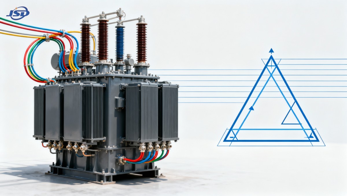
Yyn0: zero phase shift with conditions attached
Yyn0 uses star connections on both sides and has zero nominal phase displacement. Its most obvious advantage is phasor alignment: a phase on one side corresponds directly to the same phase reference on the other side. That can be useful where a zero-shift arrangement is specifically required by an existing network arrangement or by an interconnection plan.
However, a simple star-star transformer without a delta tertiary or another harmonic-control measure may be less tolerant of unbalanced loading and triplen harmonic conditions. Magnetizing current contains harmonic components, and a star-star arrangement may not provide the same internal circulating path available in a delta winding. Depending on neutral grounding and the transformer’s construction, this can contribute to neutral displacement, waveform distortion, or unstable behavior during unbalanced ground-fault conditions.
Yyn0 should therefore trigger several additional questions during technical evaluation:
- Are both neutrals accessible, and how is each neutral intended to be grounded?
- Will the secondary serve a large number of single-phase loads or nonlinear electronic loads?
- Is a delta tertiary winding provided for harmonic circulation and system stabilization?
- Does the earth-fault study model the actual grounding impedance on both sides?
- Is zero phase shift genuinely needed, or is it being assumed to make parallel operation easier?
A Yyn0 transformer can be engineered successfully, but it should be selected for a clearly defined system reason. It is not simply a neutral-capable alternative to Dyn11. In a typical low-voltage distribution application with mixed single-phase and nonlinear loads, Dyn11 often presents fewer practical complications.
Parallel operation: where “similar” transformers fail the test
When an existing transformer is being expanded, vector group becomes a gatekeeping item. Transformers intended to share a bus should normally have the same phase displacement and compatible connection arrangement. A Dyn11 transformer cannot be directly paralleled on the same secondary bus with a Dyn1 transformer, even though both are delta-star units with identical voltage ratios. Their 60-degree relative phase difference can create severe circulating currents or an effective fault condition when breakers are closed.
Compatible vector group alone is still not enough. The review should also compare voltage ratio and tap position, percent impedance, impedance ratio, X/R characteristics where relevant, kVA rating, tap-changer operating logic, grounding arrangement, and phase sequence. Different capacities can sometimes operate in parallel, but unequal impedance causes unequal load sharing. A smaller unit may become overloaded while the total bus load appears acceptable.
Before authorizing a parallel scheme, verify these points in the approved drawings and nameplate data:
- Confirm the complete vector notation, including the clock number and neutral suffixes.
- Compare actual tap positions and the available regulation range, not only nominal voltage ratio.
- Check phase sequence at defined terminals and verify that cable labeling follows the same convention.
- Review differential relay vector compensation and CT polarity drawings.
- Confirm that secondary neutral grounding arrangements will not create unintended circulating zero-sequence paths.
- Plan commissioning tests that prove phase relation before a bus tie is closed.
Do not rely on a statement that two transformers are “both 11 o’clock.” The winding side associated with the delta or star connection still matters, as does the terminal marking convention used in the project documents.
Protection and grounding implications that belong in the selection review
Vector group changes the path available to positive-, negative-, and zero-sequence components. This directly affects protection behavior. Delta windings can confine zero-sequence current to one side of the transformer, while grounded star windings can provide a return path where their neutral is connected to ground. As a result, an earth fault on one side may produce little or no line-side zero-sequence current on the other side, even though the transformer is carrying substantial positive-sequence fault current.
That behavior is neither good nor bad by itself. It must match the protection philosophy. Ground-fault relays, restricted earth-fault schemes, neutral CTs, directional elements, and transformer differential relays all depend on accurate knowledge of the transformer connections. A relay configured for a grounded-star/delta transformer will not interpret currents correctly if the installed transformer is actually delta/star in the opposite orientation.
Neutral grounding also cannot be copied from another substation without checking fault-duty and continuity requirements. A low-voltage Dyn11 secondary may be solidly grounded to obtain rapid protective-device operation. A high-voltage YNd11 neutral might be resistance grounded to limit fault current and reduce equipment stress. These choices produce different fault-current magnitudes and require different sensing arrangements.
Connection decisions for energy-storage interfaces
Energy-storage projects introduce an additional interface question because power conversion equipment usually connects to a defined AC voltage and grounding arrangement. A containerized system with a 400 V three-phase four-wire AC output may need a transformer arrangement that supports the intended low-voltage neutral and isolates zero-sequence behavior correctly from the medium-voltage network. The transformer should be selected together with the inverter connection, grounding study, protection settings, and operating mode during grid-connected and islanded conditions.
For example, the 500kW/1MWh Air Cooling Container Energy Storage System specifies 400 V AC three-phase four-wire output, 500 kW PCS capacity, and communication options that can include IEC 61850. Where this type of system is stepped up to a medium-voltage bus, a Dyn11-style distribution interface may be appropriate when the low-voltage side needs an available neutral. That is not a universal prescription: the final group must match the converter manufacturer’s isolation requirements, the site earthing arrangement, fault-current study, and any planned parallel sources.
A disciplined way to choose among the three options
Start with the bus, not the transformer catalog. Identify whether each side is three-wire or four-wire; whether line-to-neutral loads exist; where the system neutral must be established; and whether zero-sequence current should pass, be blocked, or be controlled. Then map the required phase displacement against all existing and future parallel sources.
Dyn11 is generally the strongest starting point for a conventional medium-voltage-to-low-voltage distribution transformer feeding a grounded four-wire secondary. YNd11 is more purpose-built where the high-voltage neutral must be available and the secondary can remain three-wire. Yyn0 should be reserved for cases where zero phase shift and star-star behavior are deliberately required and the design has addressed harmonic circulation, unbalance, and neutral grounding in detail.
The final approval should cite the one-line diagram, grounding philosophy, relay settings basis, and parallel-operation plan together. A vector group is a compact nameplate code, but it represents a system-level decision that reaches into commissioning procedures, fault response, power quality, and future expansion.

Get a Quote
Regardless of whether you require general advice or specific support, we are happy to help you.
Send Us Your Inquiry Today

Jinshida Electric remains committed to contributing to global energy development through professional manufacturing and superior service.