





Why ring type current transformers deliver higher accuracy under DC bias conditions
Why ring type current transformers deliver higher accuracy under DC bias conditions
Technical evaluators working on protection relay coordination, metering system validation, or grid-integration projects for renewables and industrial drives often hit a hard wall when testing CT performance: DC bias—whether from transformer inrush, half-cycle rectifier loads, or fault-current asymmetry—induces saturation that degrades ratio and phase accuracy far beyond datasheet claims. Conventional wound-core CTs frequently fail to meet Class 0.2 or 0.5 requirements under even modest DC offset (10–15%), leading to misoperation of differential relays or energy billing discrepancies. Ring type current transformers, however, consistently maintain tighter error bands under these same conditions—not because they’re “immune” to DC bias, but because their physical architecture fundamentally reshapes how magnetic flux behaves during transient saturation.
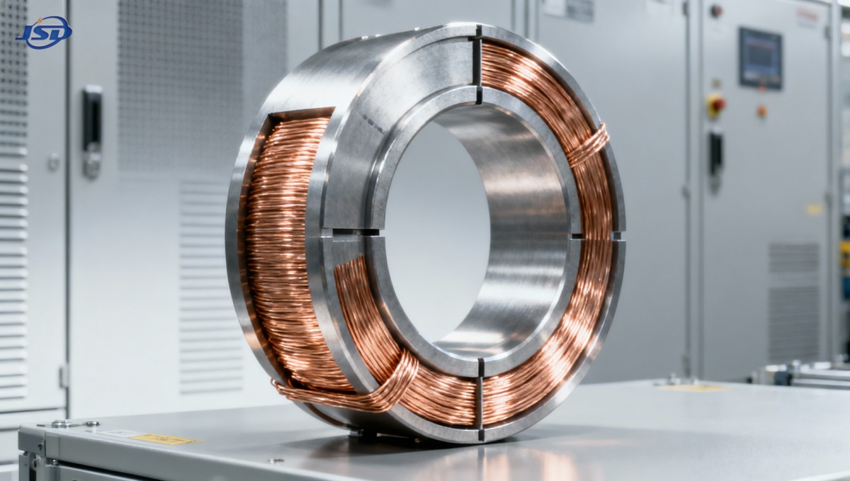
The core reason lies in the absence of air gaps and the symmetry of the magnetic path. Wound-core CTs rely on laminated cores with intentional or unavoidable joints—microscopic air gaps that become preferential paths for DC-biased flux, accelerating local saturation and introducing hysteresis-dependent phase shift. In contrast, a toroidal (ring-type) core is continuous: no joints, no stacking discontinuities, no mechanical clamping pressure variation. When DC bias superimposes on the AC excitation, the resulting flux distribution remains uniform across the entire cross-section. This delays the onset of saturation, preserves linearity over a wider operating range, and—critically—maintains predictable phase response. That predictability matters more than raw ratio accuracy alone: a 0.3% ratio error with ±15′ phase shift may still trip a high-speed bus differential relay; a 0.4% ratio error with ±3′ phase shift likely won’t.
Magnetic material choice isn’t optional—it’s decisive
Not all ring-type CTs perform equally under DC bias. The core material determines how much DC offset the unit can tolerate before accuracy degrades measurably. Silicon steel cores—common in cost-sensitive metering CTs—exhibit relatively low coercivity and saturate readily under DC bias, limiting usable dynamic range. High-permeability nanocrystalline alloys (e.g., FeCuNbSiB), by contrast, offer exceptional initial permeability (>50,000) and extremely low coercivity (<0.6 A/m), enabling stable operation up to 25–30% DC bias while retaining Class 0.2–0.5 performance per IEC 61869-2 Annex D and IEEE C57.13 Clause 5.5. Crucially, nanocrystalline’s near-rectangular B-H loop minimizes remanence after DC transients decay—reducing residual error during subsequent AC cycles. This isn’t theoretical: field measurements on 110 kV substation feeders with frequent capacitor bank switching show ring-type CTs using nanocrystalline cores sustain <0.25% composite error at 20% DC bias, whereas equivalent wound-core units exceed 1.2% error and exhibit >30′ phase deviation.
But material alone isn’t sufficient. Winding geometry matters just as much. A uniformly distributed secondary winding—critical in ring types due to lack of bobbin or former—ensures balanced ampere-turn distribution and avoids localized flux crowding. Any deviation (e.g., uneven turns, overlapping layers, or poor tension control) creates local magnetic asymmetry, reintroducing the very path non-uniformity the toroidal design seeks to eliminate. That’s why precision winding automation and post-winding core annealing are non-negotiable in high-accuracy ring-type CT manufacturing—not just quality steps, but functional prerequisites.
Where this advantage actually changes outcomes
This isn’t about marginal lab improvements. It directly impacts three high-stakes applications:
- Renewable plant interconnection: Inverter-based solar and wind farms inject significant 2nd and 3rd harmonics—and critically, produce asymmetric fault currents during ground faults. Protection CTs feeding distance or differential relays must preserve phase fidelity under DC offset to avoid blind zones or overreach. Ring-type CTs here reduce reliance on complex harmonic restraint algorithms and simplify relay settings.
- Industrial drive monitoring: VFDs generate substantial DC components in motor current waveforms, especially during startup or regenerative braking. Metering CTs feeding energy management systems (EMS) require stable ratio/phase behavior across load transients. Wound-core CTs often show 0.5–1.0% energy under-reporting during ramp-up; ring types hold within ±0.15%.
- Distribution automation: With increasing adoption of fast-acting reclosers and sectionalizers, timing margins shrink. Phase angle error >5′ at 50/60 Hz translates to >1 ms timing uncertainty—enough to flip sequence-of-events logic. Ring-type CTs provide the repeatability needed for deterministic fault location and isolation.
That said, ring-type CTs aren’t universally superior. Their installation requires conductor interruption—no split-core convenience. They also demand careful attention to external magnetic fields: unlike wound-core CTs with shielded enclosures, an unshielded toroid is sensitive to nearby busbars or grounding conductors. Proper mounting orientation and separation distance (per IEC 61869-2 Section 7.3.2) are mandatory, not optional.
What to verify—not just specify—before procurement
When evaluating ring-type CTs for DC-bias-critical applications, don’t stop at the nameplate accuracy class. Ask for:
- Test reports showing composite error (ratio + phase) at defined DC bias levels (e.g., 10%, 20%, 30%) per IEC 61869-2 Annex D, not just at rated current;
- Core material certification—nanocrystalline grade and supplier (e.g., Hitachi, VAC), not just “high-permeability alloy”;
- Winding uniformity data—typically expressed as turn-to-turn resistance variance (<±0.5% acceptable) or measured field homogeneity across the core circumference;
- Remanence test results: residual flux density (Br) after applying and removing 1.5× rated DC current, per IEEE C57.13.1 Annex C.
Avoid vendors who only quote “DC bias tolerance” without specifying test conditions (frequency, waveform, burden, temperature). Real-world DC offset rarely appears as pure DC—it’s superimposed on distorted 50/60 Hz waveforms with harmonics. Validated performance requires testing under representative conditions, not idealized sine waves.
For integrators building hybrid power systems—where battery storage interfaces directly with medium-voltage grids—the stability of current measurement becomes foundational. Consider, for example, how accurate CT data feeds into state-of-charge estimation for large-scale storage assets. A 51.2V Wall-mounted LiFePO4 Energy Storage Battery deployed in residential or light commercial PV+storage systems relies on precise current feedback for BMS balancing and grid-support functions like reactive power injection. If upstream CTs drift under DC-rich transients—say, during rapid charge/discharge cycling or islanding events—the BMS may misinterpret actual cell-level currents, compromising cycle life or safety margins. Here, ring-type CTs aren’t just “nice to have”; they close a critical measurement gap between power electronics and protection logic.
In summary: ring-type CTs deliver higher accuracy under DC bias not through marketing claims, but through intrinsic magnetic symmetry and material science rigor. Their advantage is real, measurable, and consequential—but only when specified, tested, and installed with attention to the physics that make them work. For technical evaluators, the question isn’t whether to consider them, but whether your application’s reliability threshold justifies the operational discipline they require.

Get a Quote
Regardless of whether you require general advice or specific support, we are happy to help you.
Send Us Your Inquiry Today

Jinshida Electric remains committed to contributing to global energy development through professional manufacturing and superior service.