





When Does a High-Capacity Substation Power Transformer Need Redundancy?
Redundancy is justified when the loss of one transformer would create an unacceptable operational, financial, safety, or contractual consequence. For a high capacity substation power transformer, the nameplate rating alone does not answer the question. A large transformer serving a warehouse with flexible operating hours may tolerate a planned outage; a smaller unit serving a continuous-process plant, hospital campus, data center, transit system, or critical pumping station may not.
The practical decision is therefore not “Can we afford a second transformer?” It is “What happens if the installed transformer, its associated bay, or its supply path becomes unavailable, and for how long can the business operate in that condition?” Redundancy is warranted when the credible loss scenario exceeds the organization’s tolerance for curtailed load, lost production, safety exposure, equipment damage, or delayed recovery.
Start with the consequence of losing one transformer
A power transformer outage has a different meaning in every facility. In some sites, operators can shed non-essential loads, move production to another line, run standby generation, or schedule repair during a low-demand period. In others, even a short interruption can stop a batch process, damage product, interrupt regulated services, create environmental risk, or breach customer commitments.
Decision-makers should define the consequence in operating terms before discussing transformer configurations. Questions that matter include:
- Can the site safely reduce to a partial-load operating mode?
- Which loads must remain energized: life safety, controls, communications, cooling, pumps, process protection, security, or customer-facing systems?
- How long can those loads be unavailable before losses become material?
- Can standby generation support the required loads, including starting currents and long-duration operation?
- Would an outage affect only one facility, or a wider campus, production network, or public service?
- Does the transformer feed equipment that cannot simply be stopped and restarted?
Where a single failure would stop the whole operation and no credible recovery path exists, a single-transformer substation is usually a concentrated business risk. By contrast, redundancy may be unnecessary when load interruption is manageable, restoration is straightforward, and the avoided capital cost can be better used elsewhere in the electrical system.
This distinction is important because “critical load” is often used too broadly. A facility may be commercially important without requiring every feeder, every building, and every auxiliary load to have the same availability target. Separating essential load from deferrable load often produces a more disciplined and less expensive design.
Redundancy has to cover capacity, not just equipment count
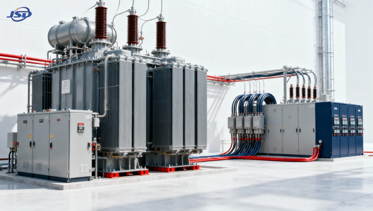
Two transformers do not automatically create meaningful redundancy. The surviving transformer, bus arrangement, cables, switchgear, protection settings, and downstream distribution system must all be able to carry the required post-contingency load.
A common planning principle is to size the system so that the loss of one major transformer still allows the site to serve its defined essential load. That may mean two transformers each capable of carrying the required emergency load, or two larger units sharing normal load with enough margin for one unit to take over after controlled load shedding. The correct approach depends on the operating profile rather than a universal percentage rule.
A surviving transformer may have a documented short-term overload capability under specified cooling and ambient conditions. That capability can be useful in a contingency plan, but it should not be treated as permanent spare capacity. Temperature rise, insulation aging, cooling-system availability, ambient temperature, load shape, and manufacturer limits all affect how long additional loading can be carried. A design that relies on emergency overload should include clear operating instructions: which loads are shed first, who authorizes the transfer, and what conditions end the temporary operating period.
Busbars and switchgear are frequently overlooked. If a tie breaker exists but the bus section, feeder equipment, or cable route cannot carry the transferred current, the arrangement may look redundant on a single-line diagram while offering little usable protection in practice. Protection coordination also changes when sources are paralleled or loads are transferred. Fault levels, transformer impedance, transformer vector groups, neutral grounding, and relay settings require review as part of the redundancy decision.
Choose the failure scenarios that the design can actually withstand
Transformer redundancy should be evaluated against credible failure modes, not an abstract assumption that one unit disappears cleanly while everything else remains available. A transformer fault can take associated high-voltage or low-voltage switchgear out of service. A cable failure, bus fault, common protection malfunction, fire event, flooding event, or loss of the incoming utility supply can defeat both transformers if they share the same vulnerable infrastructure.
For this reason, the degree of separation matters. Two transformers fed from the same source, installed in the same room, connected to the same bus without sectionalization, and dependent on one protection panel do not deliver the same resilience as two electrically and physically separated paths. That arrangement may still improve maintenance flexibility, but it should not be presented as full continuity protection against a broader substation event.
The appropriate level of separation depends on the consequence being managed. A manufacturing facility may accept two transformers in one substation with a bus tie because the primary goal is to complete planned maintenance without shutting down the entire site. A facility with strict availability obligations may need independent incoming feeders, separated transformer locations, segregated low-voltage distribution, and backup supply for controls and cooling. The design target should be stated in terms of the outage events the site intends to survive.
Do not confuse transformer redundancy with supply redundancy
Adding a second transformer does not protect against a prolonged upstream utility interruption when both units depend on the same incoming circuit or grid node. Likewise, a standby generator may keep essential systems alive but may not support the full transformer-backed load. These are separate layers of resilience.
It helps to map the electrical path from source to end use: utility incomer, high-voltage switchgear, transformer, low-voltage main switchboard, bus ties, feeders, local panels, and critical loads. At each point, ask whether a single fault can interrupt the required load and whether an alternate path exists. This exercise often shows that the best investment is not necessarily a duplicate transformer. In some cases, a sectionalized bus, an alternate feeder, targeted standby generation, or improved transfer switching addresses the dominant exposure at lower cost.
Maintenance strategy can justify redundancy even where outage costs are moderate
Large transformers require periodic condition assessment, protection testing, cooling-system checks, connection inspections, and, where applicable, fluid and insulation monitoring. Some activities can be completed while energized or during short planned interruptions. Others require isolation. If the only transformer must be removed from service for work, the site either accepts the outage or arranges temporary power.
Temporary generation and rental transformer plans deserve scrutiny before they are relied upon. Logistics, site access, transformer transport, compatible voltage and impedance, cable routing, switching authority, fuel arrangements, and commissioning time can make a theoretically available contingency plan difficult to execute under pressure. A high-capacity unit is not interchangeable with any available spare transformer, particularly where voltage ratio, vector group, fault duty, tap range, protection interface, or physical footprint differ.
A second installed transformer can reduce the operational pressure surrounding maintenance, but only if isolation and transfer can occur safely. The operating procedure should define whether the system is intended for open-transition transfer, closed-transition transfer, or a controlled shutdown. It should also identify the interlocks, synchronization requirements, grounding arrangements, and approved switching sequence. Redundancy without a tested transfer procedure remains a design intention rather than an operating capability.
Future load growth changes the answer faster than many capital plans assume
High-capacity substations are often built around expected expansion. Electrified heating, additional production equipment, charging infrastructure, new data loads, and process upgrades can consume contingency margin earlier than forecast. The risk is not merely that demand grows beyond the original transformer rating. It is that the system remains apparently oversized in normal operation while no longer meeting the essential-load target after one transformer is lost.
Load forecasts should distinguish between approved projects, likely projects, and speculative opportunities. The first group belongs in the base case. The second should be tested as a planning case. The third may justify physical space, bus provisions, and protection expansion capability without forcing immediate investment in duplicate installed capacity.
For facilities expanding in stages, it can be sensible to build the substation layout, civil works, and switchgear interfaces for a future second transformer while initially installing one unit. That strategy is appropriate only where the interim single-transformer risk is accepted and the future installation can be completed without unacceptable disruption. It is less suitable when continuity is needed from the first day of operation.
Dry-type distribution transformers can support a layered resilience design
Not every redundancy decision belongs at the largest transformer level. A site may use a primary substation transformer for bulk supply while protecting selected downstream loads with separate distribution paths. In buildings where fire performance, indoor installation, and localized load continuity influence the design, dry-type transformers can be part of that lower-voltage strategy.
For example, a 35kV Three-Phase Cast Resin Dry-Type Distribution Transformer can be relevant where a 35 kV to 0.4 kV distribution arrangement serves critical sections of an industrial plant, hospital, commercial building, data center, mining operation, or renewable-energy facility. Its role should be assessed within the full architecture: rated capacity, cooling method, fire requirements, temperature protection, fault coordination, and the ability of alternate feeders to carry essential loads. A transformer capable of temporary increased loading under forced-air cooling may assist contingency operation, but it does not remove the need to define duration limits and downstream bottlenecks.
This layered approach can avoid overbuilding the entire system. Instead of designing every load for full duplication, the organization can protect the loads that have the highest consequence of interruption and allow non-critical functions to shed during an abnormal condition.
Compare the cost of redundancy with the cost of recovery
The capital cost of a second transformer includes more than the transformer itself. It may require additional bays, circuit breakers, bus sections, cable capacity, civil works, fire separation, protection and control panels, metering changes, commissioning, and ongoing maintenance. In some designs, the upstream network connection and downstream switchboard rating also need to increase.
Those costs should be compared with the full cost of an outage, not simply lost electricity consumption. The business case may include lost production, spoiled material, restart labor, equipment recovery, contractual penalties, missed service commitments, safety exposure, and the time needed to procure, deliver, install, and test a replacement. Replacement lead time matters because a severe transformer failure can create a long recovery window even when repair is technically possible.
The decision should also account for risk reduction that is operationally real. A duplicate unit that cannot be switched in quickly, cannot carry the required load, or shares the same failure exposure should not receive the same value as a properly separated and tested alternate path.
A practical decision test before committing capital
Redundancy is generally justified when four conditions align: the load is critical enough that interruption is unacceptable; the surviving system can demonstrably carry the essential demand; the alternate path avoids the most credible common failure points; and the expected cost of outage and recovery is greater than the lifecycle cost of providing and maintaining the additional capacity.
Where one of these conditions is missing, the answer may be a narrower resilience measure rather than a fully duplicated high capacity substation power transformer. Define the essential-load envelope, model the loss-of-transformer condition, inspect common-mode vulnerabilities, and validate the transfer process with the people who will operate it. That produces a redundancy decision tied to business continuity rather than a generic preference for more equipment.

Get a Quote
Regardless of whether you require general advice or specific support, we are happy to help you.
Send Us Your Inquiry Today

Jinshida Electric remains committed to contributing to global energy development through professional manufacturing and superior service.