





Understanding Core and Copper Losses in a Low Loss Distribution Transformer
Understanding Core and Copper Losses in a Low Loss Distribution Transformer
For technical evaluators, understanding core and copper losses is essential when assessing a low loss distribution transformer. These losses directly affect efficiency, temperature rise, lifecycle cost, and network reliability.
This article explains how magnetic materials, core geometry, winding design, loading conditions, and manufacturing controls influence loss performance in distribution, industrial, renewable, and infrastructure applications.
Why Loss Evaluation Must Go Beyond Nameplate Efficiency
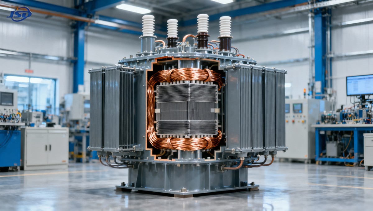
A transformer may show high efficiency at one test point while producing materially different annual energy costs under actual loading, ambient conditions, voltage variation, and operating schedules.
Technical evaluators should separate no-load loss from load loss before comparing quotations. Each loss category has different causes, operating behavior, financial consequences, and optimization opportunities.
No-load loss occurs whenever the transformer is energized, even without a connected load. It is therefore especially important for lightly loaded assets operating continuously throughout the year.
Load loss rises as current increases and becomes increasingly important in transformers supporting industrial machinery, charging infrastructure, dense commercial facilities, and fluctuating renewable-energy-connected loads.
A low loss distribution transformer should be assessed against the expected load profile, not only against a generic efficiency figure. Annualized loss energy provides a stronger comparison basis.
Evaluators should request guaranteed no-load loss, guaranteed load loss at the specified reference temperature, impedance tolerance, temperature-rise data, and supporting routine test documentation.
The lowest purchase price can become expensive when a transformer remains energized for decades. Loss capitalization converts expected energy waste into a measurable procurement comparison.
Loss evaluation also affects substation ventilation, cable sizing, protection coordination, room temperature, maintenance planning, and the usable capacity available during sustained high-demand operating periods.
Core Loss: The Continuous Energy Cost of Magnetizing the Transformer
Core loss, also called iron loss or no-load loss, is generated when alternating magnetic flux repeatedly magnetizes and demagnetizes the transformer core steel.
It consists primarily of hysteresis loss and eddy-current loss. Both occur whenever rated or near-rated voltage is applied, regardless of secondary loading level.
Hysteresis loss reflects energy consumed while magnetic domains change direction during each alternating-current cycle. Lower-loss magnetic steel reduces the energy required for this process.
Eddy-current loss is caused by circulating currents induced within the core material. Thin insulated laminations restrict these currents and reduce associated heating.
Grain-oriented silicon steel remains a common choice because its crystal structure supports efficient magnetic flux travel in the rolling direction under controlled manufacturing conditions.
Amorphous alloy cores can achieve substantially lower no-load losses, particularly where transformers remain energized around the clock and average loading remains modest.
However, core material selection is not purely a material-cost decision. Mechanical characteristics, noise behavior, dimensional design, supply availability, and manufacturing expertise also matter.
For many utility and infrastructure projects, conventional high-grade grain-oriented steel provides a practical balance between loss reduction, robustness, procurement flexibility, and total installed cost.
Core losses are sensitive to flux density. Increasing flux density can reduce material volume and initial cost, but it generally increases no-load loss, noise, and saturation risk.
A conservative magnetic design can provide better efficiency and voltage resilience, particularly where grid voltage may remain above nominal levels for extended intervals.
Frequency also matters. A transformer designed for 50 Hz must not automatically be evaluated as suitable for 60 Hz operation, or vice versa, without confirming flux-density limits.
Voltage waveform quality deserves attention in facilities with nonlinear loads. Harmonic voltage content can increase core heating beyond assumptions used in standard sinusoidal loss testing.
How Core Construction Determines Real No-Load Performance
Even premium steel cannot guarantee low core loss when cutting, stacking, clamping, annealing, and joint assembly introduce stress or disturb magnetic alignment.
Mechanical stress changes magnetic properties in electrical steel. Poor handling during fabrication can therefore increase loss beyond values expected from the material datasheet.
Step-lap joints are commonly used to improve flux transfer between laminations. They reduce localized magnetic reluctance and can lower no-load current, loss, and audible noise.
Joint precision is important because small gaps force magnetic flux through less favorable paths. This can increase excitation current and concentrate heating near joints.
Proper annealing relieves stresses introduced by cutting and processing. Evaluators should ask whether core processing controls are standardized, documented, and consistently applied in production.
Core clamping requires balance. Insufficient restraint can allow vibration, while excessive pressure can damage laminations or create stress-related magnetic performance deterioration.
Noise measurements provide useful supporting evidence because magnetostriction and mechanical vibration often reveal core design or assembly issues, although noise alone does not define loss.
Factory no-load testing should confirm the guaranteed loss value at stated voltage and frequency. Test reports should identify measurement conditions and applicable test standards clearly.
When comparing suppliers, a guaranteed maximum loss value is more meaningful than a typical value. Procurement contracts should define acceptance criteria and remedies for noncompliance.
Copper Loss: The Load-Dependent Constraint on Transformer Capacity
Copper loss is principally the resistive heating produced by current flowing through primary and secondary windings. It is commonly described using the I-squared-R relationship.
When load current doubles, resistive winding loss increases approximately fourfold. This nonlinear behavior makes load forecasting essential for technically defensible transformer selection.
The term copper loss is widely used, although windings may use copper or aluminum conductors. The underlying issue is conductor resistance and resulting heat generation.
Copper offers lower electrical resistivity than aluminum, enabling smaller conductor cross-sections for equivalent resistance. Aluminum can still be effective when correctly sized and properly terminated.
Evaluators should avoid treating conductor material as a simple quality ranking. Winding geometry, conductor area, joints, insulation system, cooling design, and workmanship determine actual performance.
Load loss measured during routine testing includes winding resistance loss and may include additional stray losses created by leakage flux in windings, structural components, and tank walls.
Stray losses become more important at larger ratings or where high-current winding arrangements create substantial leakage flux. Poor electromagnetic design can increase localized heating significantly.
A low loss distribution transformer uses conductor cross-sections and winding configurations that limit resistance without compromising insulation clearances, mechanical strength, short-circuit capability, or manufacturability.
Reducing winding resistance often requires more conductive material. The correct design balances initial investment against annual energy savings and expected operating duty.
For heavily loaded industrial transformers, lower load loss may offer greater lifecycle value than an exceptionally low no-load loss design. The reverse may apply to lightly loaded networks.
Temperature, Impedance, and Winding Design Need Joint Review
Winding resistance increases as conductor temperature rises. Therefore, load loss stated at a standard reference temperature may differ from actual losses during normal site operation.
Technical evaluations should confirm the reference temperature used for quoted load loss. Comparing values measured or calculated at different temperatures can produce misleading conclusions.
Temperature rise is not merely a thermal compliance figure. It affects insulation aging, conductor resistance, cooling requirements, reliability margins, and long-term operating cost.
Lower losses generally reduce internal heat generation, but cooling design determines whether that advantage translates into acceptable winding and oil temperatures under site conditions.
Oil-immersed designs rely on effective heat transfer through windings, insulating liquid, radiators, and ambient air. Uneven flow paths can create hot spots despite acceptable average temperature rise.
Dry-type designs require equally careful review of airflow, enclosure class, harmonic loading, altitude derating, and contamination exposure, especially in industrial indoor installations.
Transformer impedance affects fault current, voltage regulation, and load sharing. A low-loss design should not sacrifice required impedance characteristics simply to reduce winding resistance.
Very low impedance may create excessive fault duty or operational voltage behavior. Evaluators should assess efficiency alongside system protection studies and voltage-drop requirements.
Mechanical winding strength is also essential. Conductors and clamping systems must withstand short-circuit forces, since deformation can raise losses and compromise insulation after a fault event.
Match Loss Priorities to the Actual Load Profile
The most useful procurement model calculates annual energy loss using expected energization hours, hourly or seasonal load distribution, electricity cost, and projected operating life.
No-load energy loss can be estimated by multiplying no-load loss by annual energized hours. This usually approaches 8,760 hours for continuously connected transformers.
Load-loss energy requires a load factor calculation because winding loss varies with the square of current. Average load alone is often insufficient for accurate estimates.
A facility with brief but high peak demand may have lower annual copper-loss energy than another facility with a similar average load but consistently elevated current.
Renewable projects require particular attention because generation output may vary sharply. Daytime export, nighttime auxiliary demand, curtailment patterns, and storage dispatch change transformer loading behavior.
Commercial facilities with stable daytime use may prioritize a balanced loss design. Remote utility substations with low utilization may place greater value on minimizing continuous core loss.
Industrial plants operating near transformer capacity for multiple shifts often benefit from lower load loss, provided the selected rating and cooling system maintain suitable thermal margins.
Network expansion plans should be included in the evaluation. A transformer optimized only for current low loading may become uneconomic when load growth changes the loss balance.
Where expansion is uncertain, evaluators can model several scenarios: low utilization, expected utilization, and high utilization. This makes design tradeoffs visible before purchase approval.
How Energy Storage Changes Distribution Transformer Assessment
Energy storage can change transformer loading patterns by absorbing power during low-demand periods and discharging during peaks, reducing overload exposure or creating new bidirectional flow conditions.
For commercial and industrial projects, storage integration should be reflected in transformer studies rather than treated as a separate electrical package with unrelated performance assumptions.
A containerized system such as the 500kW/1MWh Air Cooling Container Energy Storage System can support peak shaving, photovoltaic energy storage, backup supply, and microgrid operating strategies.
Its 500 kW power capability and 1 MWh capacity may reduce demand peaks, but actual transformer benefits depend on dispatch settings, charging windows, site load shape, and interconnection arrangement.
Storage charging can increase transformer current during off-peak hours. Evaluators should verify that scheduled charging does not create unexpected copper losses or exceed thermal limits.
Bidirectional power flow may also influence tap-setting strategy, protection coordination, metering arrangement, and voltage regulation. These effects require project-specific electrical studies.
Harmonics from power conversion equipment should be assessed using manufacturer data and system analysis. Harmonic currents can increase winding eddy losses and local heating.
Appropriate transformer design may include harmonic capability considerations, thermal derating analysis, shielding arrangements, or specified limits for total harmonic distortion at the connection point.
What to Request from Suppliers During Technical Evaluation
A strong technical specification defines rated power, voltage ratio, vector group, impedance, tap range, insulation class, cooling method, temperature rise, and applicable efficiency requirements.
It should also state maximum guaranteed no-load loss and load loss, including the reference temperature for load loss and the test method used for verification.
Request routine test reports for each supplied unit. These should include winding resistance, voltage ratio, vector group, short-circuit impedance, no-load current, and loss measurements.
For critical projects, consider witness testing or third-party inspection. Independent observation is valuable where loss guarantees materially affect project economics or contractual acceptance.
Ask suppliers to identify the core material grade, lamination processing approach, winding conductor material, insulation system, cooling configuration, and quality-control process used in manufacturing.
Manufacturing consistency matters as much as prototype performance. A supplier should demonstrate controlled processes that reproduce guaranteed loss levels across the complete delivery batch.
Technical reviewers should also examine tolerance statements. A transformer meeting nominal rating but exceeding loss expectations can undermine lifecycle cost assumptions established during project approval.
Clarify site conditions, including altitude, ambient temperature, installation enclosure, ventilation, pollution level, seismic requirements, and expected harmonic content before finalizing the transformer design.
These conditions can affect temperature rise and usable capacity. A low loss distribution transformer must remain low risk when installed, not merely perform well in a factory test environment.
Use Lifecycle Cost Instead of Initial Price Alone
Lifecycle cost evaluation converts transformer losses into financial terms, allowing procurement teams to compare alternatives with different purchase prices and different long-term energy consumption.
A simplified model combines acquisition cost, annual no-load energy cost, annual load-loss energy cost, maintenance expectations, downtime risk, and expected service life.
Loss capitalization factors can be used when organizations have established energy-price forecasts, discount rates, operating-hour assumptions, and asset-life policies for capital investment decisions.
The calculation should be transparent. Inputs that remain hidden inside a supplier proposal make it difficult to test sensitivity to electricity prices, load growth, or utilization changes.
Evaluators should model at least one higher-energy-price scenario. Loss reductions often become more valuable over time, especially for transformers energized continuously in long-life infrastructure assets.
Reliability has economic value as well. Reduced temperature stress can support insulation longevity, lower cooling burden, and greater resilience during sustained loading, although each benefit requires design evidence.
The best selection is not always the transformer with the lowest published losses. It is the unit that meets electrical, thermal, mechanical, operational, and commercial requirements at defensible lifecycle cost.
Final Evaluation Perspective
Core loss is a continuous cost driven by magnetic design and core manufacturing quality. Copper loss is a load-dependent cost driven by winding resistance, leakage flux, and temperature.
Technical evaluators should compare guaranteed values, verified test data, expected load profiles, site conditions, harmonic exposure, and lifecycle economics before selecting a low loss distribution transformer.
This approach prevents narrow nameplate comparisons and supports more reliable investment decisions for grids, industrial facilities, renewable projects, infrastructure systems, and energy-storage-connected distribution networks.

Get a Quote
Regardless of whether you require general advice or specific support, we are happy to help you.
Send Us Your Inquiry Today

Jinshida Electric remains committed to contributing to global energy development through professional manufacturing and superior service.