





Transformer Protection Strategies for Remote Distribution Transformers in Mining Sites
Transformer Protection Strategies for Remote Distribution Transformers in Mining Sites
Remote mining operations live with a power problem that urban industrial plants rarely face: the electrical system must remain dependable even when access is difficult, ambient conditions are severe, and a relatively small fault can interrupt an entire production chain. A failed distribution transformer may stop conveyors, pumping systems, communications, ventilation, crushing equipment, workshops, or underground auxiliary loads. In a remote location, the repair itself is only part of the problem. Mobilizing technicians, lifting equipment, replacement parts, and transport can take far longer than the electrical fault investigation.
For project leaders, transformer protection should therefore be treated as a system design decision rather than a relay-setting exercise completed near commissioning. The best approach for distribution transformers for mining sites considers the source network, transformer construction, protection coordination, installation environment, operating profile, and realistic maintenance capability at the site. A technically correct transformer can still become a weak point if it is installed where dust accumulates, cable terminations are inaccessible, or overload alarms are not seen until the unit has already overheated.
Start with the mine’s actual failure exposure
Mining loads are rarely calm or uniform. Large motors can create high starting currents and voltage dips. Variable-speed drives, rectifiers, and other power-electronic equipment may introduce harmonic distortion. Long feeder runs can complicate fault discrimination, especially where the transformer is supplied through overhead lines or temporary construction networks. At open-pit sites, exposure to dust, windblown sand, rain, heat, and mobile plant damage may dominate the risk profile. Underground, moisture, confined spaces, ventilation limitations, and difficult evacuation routes often demand a different protection philosophy.
The first practical question is not “Which relay should we buy?” It is: what is most likely to damage this transformer or leave this load area without power? Common answers include sustained overloading during production expansion, external short circuits, insulation degradation caused by heat and contamination, phase imbalance, loose terminations, lightning exposure on remote overhead feeders, and accidental mechanical contact with cables or transformer enclosures.
A useful early design review separates faults into three groups. Internal transformer faults require rapid isolation. Downstream faults should be cleared selectively, without unnecessarily tripping the upstream mine substation. Gradual deterioration—high temperature, reduced oil quality, repeated overload, or worsening cable connections—should produce alarms early enough for planned intervention. Those three goals require different devices and different operating logic.
Coordinate protection instead of simply adding more devices
More protective equipment does not automatically mean a more resilient system. Poorly coordinated devices can turn a local feeder fault into a site-wide outage. Protection studies should establish which breaker, fuse, relay, or recloser operates first for each credible fault location. The transformer’s inrush current, available fault level, feeder impedance, motor starting behavior, and earthing arrangement all affect that study.
For a typical medium-voltage distribution transformer, the protection package may include primary-side overcurrent and earth-fault protection, secondary-side breaker protection, surge arresters, temperature monitoring, and transformer-specific internal fault detection where the transformer type and criticality justify it. Oil-filled units may use devices such as pressure relief equipment and gas-actuated protection, depending on design and application. Dry-type transformers commonly rely more heavily on winding temperature sensors and thermal protection logic. The exact arrangement should follow the transformer design, local electrical rules, and the project’s approved protection philosophy.
One recurring mistake is setting overcurrent protection tightly enough to trip during normal motor acceleration or transformer energization. Another is allowing settings so high that the transformer absorbs damaging thermal energy before the upstream device clears a fault. Neither issue can be solved from nameplate data alone. Time-current coordination needs the actual feeder layout and expected operating sequence, particularly when pumps and crushers start after a power restoration.
Environmental protection is electrical protection
At mine sites, many transformer problems begin outside the tank or enclosure. Dust can restrict cooling surfaces and contaminate bushings. Salt-laden air at coastal operations can accelerate corrosion. High solar exposure can raise enclosure temperatures well above the surrounding air temperature. In cold regions, condensation and repeated freeze-thaw cycles can affect cable entries, seals, and marshalling boxes. A transformer selected only by voltage and kVA rating may be unsuitable before it is even energized.
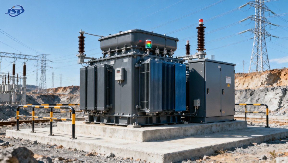
Placement matters. Transformers should be located away from haul-road impact zones, drainage paths, blasting vibration where practical, and areas where fine dust is routinely discharged. The site should preserve working clearance for inspection and replacement, rather than placing a unit behind fixed process equipment because that location was convenient during civil construction. For outdoor installations, robust plinth design, drainage, cable trench sealing, appropriate enclosure protection, and physical barriers against vehicle impact are usually worth addressing upfront.
Cooling deserves particular attention. A transformer may have sufficient capacity on paper but operate close to its thermal limit if radiators are dirty, ventilation paths are blocked, or a kiosk is poorly ventilated. Thermal loading assumptions should be reviewed whenever the mine adds pumps, extends a camp, upgrades a processing line, or changes the duty cycle of electrically driven equipment. “Temporary” loads frequently become permanent loads in mining projects.
Build visibility for a site that cannot inspect every asset daily
Remote monitoring is most valuable when it supports decisions, not when it simply creates another screen of data. At a minimum, the operations team should know whether the transformer is energized, carrying unusual load, approaching a temperature limit, or showing a protection alarm that requires attention. For critical transformers, monitoring may include load current, voltage, winding or oil temperature where applicable, enclosure conditions, breaker position, relay events, and communication health.
Communication architecture must be planned with the same care as protection hardware. A remote terminal unit that loses its network during a feeder disturbance may leave operators blind at the moment they need information most. Local alarm indication, event records in protection relays, and a defined fallback inspection process remain important. There is no benefit in specifying sophisticated diagnostics if the site has no practical way to review, interpret, or act on them.
Where the mine uses distributed generation or unstable utility supply, power quality monitoring may also be justified. Repeated undervoltage, voltage unbalance, or abnormal harmonic conditions may not immediately trip a transformer, but they can reveal a growing issue in the wider network. The relevant thresholds should be set by the electrical design team and matched to the connected equipment rather than copied from a generic template.
Use energy storage selectively for control and recovery loads
Battery storage is not a substitute for properly protected distribution transformers, nor is it intended to carry every mining load through a long outage. It can, however, be useful at the low-voltage edge of the system. Small, well-defined storage systems may support communications, control power, monitoring equipment, gate systems, lighting, or orderly shutdown sequences while the main transformer supply is unavailable. In off-grid auxiliary facilities, storage may also smooth the operating relationship between solar generation, inverter systems, and essential low-voltage loads.
For such applications, a modular option such as the 51.2V Stackable LiFePO4 Energy Storage Battery can be evaluated where its 5.12 kWh module capacity, expandable configuration, CAN/RS485 communication, and operating temperature range of -10°C to +55°C fit the auxiliary power design. Its IP21 rating also makes location important: it is better suited to an appropriately protected indoor or enclosed installation than an exposed mining yard. The battery system, inverter, DC protection, ventilation, fire strategy, and local installation requirements must be engineered as one package.
Make maintenance possible, not merely required
A maintenance plan that depends on specialist attendance every time an alarm occurs is fragile in remote mining. The preferred strategy is to combine routine local checks with clear escalation criteria. Site electricians should be able to inspect for oil leakage where relevant, unusual noise, damaged bushings, contaminated insulators, loose external connections, blocked airflow, enclosure corrosion, and evidence of overheating. They should also know which conditions require the transformer to be isolated rather than kept in service until a visiting specialist arrives.
Spare planning should reflect lead time and criticality. Keeping a full spare transformer is not always economically sensible, especially where ratings vary across the site. Yet relying on an overseas replacement with no contingency can be equally risky for a production-critical unit. Some projects choose a common transformer rating across multiple auxiliary areas, retain compatible bushings and protection components, or design switching arrangements that allow essential loads to be transferred temporarily. These are project-specific trade-offs, but they should be made deliberately.
Procurement decisions that affect protection performance
The transformer manufacturer should receive more than a voltage, power rating, and vector group. A meaningful technical inquiry normally includes installation altitude, ambient temperature range, indoor or outdoor location, dust and moisture exposure, source fault level, earthing method, expected load profile, harmonic-producing loads, cable connection requirements, requested monitoring points, and applicable project standards. If the unit will be moved as the mine develops, transport and lifting constraints should be stated early as well.
Jinshida Electric Power Technology Co., Ltd. approaches power transmission and distribution equipment through the combined requirements of product design, manufacturing control, and field application. For mining-related projects, that practical combination matters: protection features must be compatible with the selected transformer, while the transformer itself must suit the operating environment and maintenance reality. Detailed technical clarification before manufacture is generally more valuable than attempting to solve installation conflicts after delivery.
The strongest protection strategy for remote distribution transformers is usually not the most elaborate one. It is the one that isolates real faults quickly, avoids unnecessary trips, withstands the mine environment, gives operators usable warning, and can be maintained with the people and resources actually available on site. Before finalizing equipment, review the one-line diagram, protection coordination study, physical layout, monitoring signals, and emergency switching procedure together. That review often reveals the weak link long before the mine has to discover it during an outage.

Get a Quote
Regardless of whether you require general advice or specific support, we are happy to help you.
Send Us Your Inquiry Today

Jinshida Electric remains committed to contributing to global energy development through professional manufacturing and superior service.