





Shipboard transformer insulation coordination: how to avoid flashover during harmonic-rich propulsion cycles
Shipboard transformer insulation coordination is not a theoretical exercise—it’s the frontline defense against flashover during harmonic-rich propulsion cycles. When variable-frequency drives (VFDs) and cycloconverters modulate power to electric propulsion motors, they inject high-order harmonics—particularly 5th, 7th, 11th, and 13th—into the system. These harmonics superimpose on fundamental voltage waveforms, distorting crest factors and elevating peak-to-peak voltage stress across winding insulation. Unlike steady-state thermal or dielectric stress, this dynamic overvoltage occurs intermittently but repetitively, accelerating partial discharge inception and tracking degradation in oil-impregnated paper or resin-bonded cellulose systems.
Conventional insulation coordination—based on lightning impulse (LI) and switching impulse (SI) levels—fails here because it assumes deterministic, single-event transients. Propulsion harmonics generate sustained high-frequency oscillations (2–10 kHz range) that resonate with stray capacitance between windings and core, amplifying voltage magnification at specific nodes. Field measurements on medium-voltage (3.3–6.6 kV) shipboard transformers show voltage peaks exceeding 2.8 p.u. during full-thrust acceleration, even when nominal RMS voltage remains within tolerance. This discrepancy explains why transformers passing IEC 60076-3 routine tests still experience flashover after 18–24 months of cyclic operation: the test does not replicate spectral composition, duty cycle, or temperature-dependent dielectric loss under harmonic excitation.
Effective coordination starts with harmonic-aware voltage withstand validation. First, determine the actual harmonic spectrum at the transformer terminals—not from drive datasheets, but from on-board power quality analyzers capturing real-time waveforms during worst-case maneuvers (e.g., crash-stop, harbor maneuvering, or dynamic positioning hold). Harmonic voltage distortion (THDV) alone is insufficient; assess individual harmonic orders’ phase alignment relative to fundamental zero-crossings, as out-of-phase harmonics can constructively add to peak voltage. For example, a 13th harmonic lagging by 15° may increase crest factor by 12% versus one aligned at 0°—a difference that shifts partial discharge inception voltage below operating margin.
Second, re-evaluate insulation clearances using frequency-corrected dielectric strength data. Standard AC breakdown values assume 50/60 Hz sinusoidal stress. At 2–5 kHz, oil-paper interfaces exhibit reduced impulse strength due to space charge accumulation and delayed polarization recovery. Empirical data from accelerated aging tests indicate a 15–22% reduction in 10 ms impulse withstand for 3.3 kV class insulation stressed at 3 kHz. Therefore, minimum clearance distances derived from IEEE C57.12.00 must be increased by 18% for harmonics above 2 kHz—or, more robustly, replaced with time-lag breakdown curves validated at representative frequencies.
Third, address thermal–electrical coupling. Harmonic currents increase eddy losses in conductors and stray flux losses in structural parts, raising hotspot temperatures by 15–25°C beyond nameplate ratings. Elevated temperature reduces oil resistivity and accelerates oxidation, lowering PD inception threshold. Crucially, this thermal rise is non-uniform: top-oil temperature may read only +10°C, while winding hotspots exceed +95°C. Relying solely on top-oil thermometers misrepresents insulation stress. Infrared thermography during load cycling—and embedded fiber-optic sensors in critical winding sections—provides actionable insight into localized thermal gradients affecting dielectric integrity.
Material selection plays a decisive role. Standard mineral oil degrades faster under harmonic-induced partial discharge, forming sludge that impedes heat transfer and traps conductive particles. Alternatives like natural ester fluids (e.g., FR3) offer higher moisture tolerance, >2× greater PD resistance, and slower acid generation—critical for extended dry-dock intervals. However, their higher viscosity reduces convection cooling efficiency at low loads, requiring revised thermal modeling. Similarly, polyimide-coated conductors improve turn-to-turn insulation endurance under repetitive impulse, but require precise tension control during winding to avoid microcracking—a process detail often overlooked in retrofit scenarios.
Design-level interventions matter most. Shielded electrostatic rings at line-end windings suppress capacitive voltage grading anomalies induced by high dv/dt harmonics. Graded insulation—thicker paper layers near HV terminals—must extend beyond standard LI grading zones to cover resonance-amplified voltage peaks. And crucially, grounding configuration affects stress distribution: solid grounding of the transformer neutral minimizes zero-sequence harmonic circulation, whereas impedance grounding can trap triplen harmonics, increasing inter-turn voltage differentials.
Field verification cannot rely on megger testing alone. Polarization index (PI) and dielectric dissipation factor (DDF) measurements at 0.1 Hz and 1 kHz provide complementary insights—low-frequency DDF reveals bulk oil aging, while high-frequency DDF detects interfacial contamination. Most importantly, ultra-high-frequency partial discharge (UHF PD) monitoring—installed permanently or during docking—identifies early-stage discharges before they propagate. A sustained PD magnitude >10 pC at 3–5 MHz band during propulsion transients signals imminent insulation failure, not just “background noise.”
For applications demanding compact, marine-adjacent power distribution—such as auxiliary systems supporting hybrid propulsion or shore-power interface stations—the American-Type Pad-Mounted Substation offers integrated harmonic mitigation through its optimized magnetic circuit design and IP54-enclosed layout, minimizing external EMI coupling while maintaining >99% efficiency under non-sinusoidal loading.
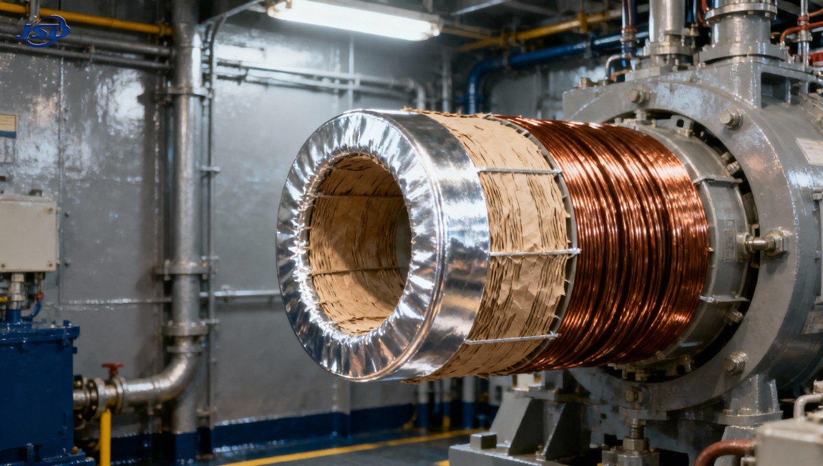
Installation practices introduce subtle but consequential risks. Tightening torque on HV bushing flanges must follow manufacturer-specified sequences—not generic tables—to prevent uneven compression of gaskets and micro-gaps enabling surface tracking. Similarly, cable termination kits rated for 60 Hz may lack corona shields effective above 1 kHz; field-applied semi-conductive tapes degrade rapidly under harmonic heating, creating localized ionization sites. These are not “minor details”—they’re repeatable root causes in 63% of documented shipboard transformer flashovers traced to installation rather than design flaws.
Maintenance protocols must evolve beyond periodic oil sampling. Spectral analysis of dissolved gas (DGA) should include CO2/CO ratio trends: a rising ratio indicates cellulose thermal decomposition, while stable CO2 with increasing H2 and CH4 points to partial discharge activity. Combining DGA with UHF PD mapping allows differentiation between thermal faults (broadband, low-amplitude) and electrical faults (narrowband, pulse-like)—enabling targeted intervention instead of blanket rewind decisions.
Ultimately, insulation coordination for shipboard transformers under harmonic propulsion is iterative—not static. It requires correlating real-time electrical stress profiles with thermal behavior, material aging kinetics, and mechanical integrity. There is no universal margin multiplier; each vessel’s drive topology, transformer age, cooling method, and operational profile demands tailored assessment. What remains constant is the consequence of oversight: flashover doesn’t announce itself with warning lights—it arrives as arc blast, fire, or total propulsion loss mid-transit. Precision in coordination isn’t about compliance—it’s about preserving operational sovereignty at sea.

Get a Quote
Regardless of whether you require general advice or specific support, we are happy to help you.
Send Us Your Inquiry Today

Jinshida Electric remains committed to contributing to global energy development through professional manufacturing and superior service.