





1500 kVA ONAN Transformer Loading in High Ambient Temperatures
A 1500 kVA ONAN transformer does not have a universal hot-weather loading limit. It may carry its full nameplate load at a high ambient temperature if it was designed for those conditions, but a unit rated for a cooler environment may require derating. The deciding factors are the temperature of the air reaching its cooling surfaces, its thermal design, its recent load history, and the winding hot-spot temperature—not the outdoor weather reading alone.
When site temperatures exceed the transformer’s specified service conditions, full-load operation should not be treated as automatically acceptable. Equally, a fixed rule such as “reduce capacity by 10% above 40°C” is not a reliable substitute for manufacturer data. A defensible loading limit must account for both the immediate temperature risk and the insulation aging caused by sustained operation.
Establish what the 1500 kVA rating actually permits
ONAN means oil natural, air natural: heat moves through the oil by natural circulation and leaves the tank or radiators through natural air circulation. The transformer therefore depends on an unobstructed heat path from the windings to the surrounding air. A nameplate capacity of 1500 kVA describes its rated apparent power under specified conditions; it is not a guarantee of that capacity at every ambient temperature or installation arrangement.
Before changing the operating limit, check the nameplate, technical specification, temperature-rise test report, and manufacturer’s loading instructions. The important details include:
- The specified maximum ambient temperature and any restrictions on daily or seasonal temperature averages.
- The rated top-oil and winding temperature rises, together with the insulation system and cooling configuration.
- The installation altitude and indoor or outdoor service conditions.
- Any approved loading curves, overload durations, or special high-temperature rating.
- The temperature alarm and trip settings established for the particular unit.
A maximum ambient figure does not necessarily mean the transformer can operate continuously at that temperature under every load profile. Daily averages, previous loading, and thermal equilibrium also matter. Conversely, a transformer specifically designed for a hot climate may retain its rated capacity where a standard-design unit would need a lower operating limit.
For mineral-oil-immersed transformers, IEC 60076-7 provides a framework for assessing loading, temperature, and insulation aging. IEEE C57.91 is another relevant loading guide where applicable. These are calculation frameworks, not universal percentage-derating tables. Their application requires suitable transformer parameters and agreement with the equipment’s design and operating requirements.
Measure the ambient temperature that affects cooling
A weather station reading can understate the temperature around the transformer. In an indoor substation, restricted ventilation can allow heated air to accumulate. Outdoors, nearby walls, other heat-producing equipment, and recirculation of warm air can impair cooling. Solar radiation adds heat to exposed surfaces even when the measured air temperature remains unchanged.
Use a suitably positioned, shielded temperature sensor to measure representative cooling-air temperature near the transformer, away from direct sunlight and hot discharge air. For enclosed installations, compare the incoming ventilation air with the air around the tank and radiators. A single sensor mounted against a sun-heated wall is not a dependable ambient reference.
Inspect the cooling path as well as the thermometer. Dust-covered radiator surfaces, blocked ventilation openings, inadequate clearances, and stored materials around the transformer can all reduce heat rejection. Check radiator valve positions where applicable, but do not operate valves or alter the oil circuit without an authorized procedure.
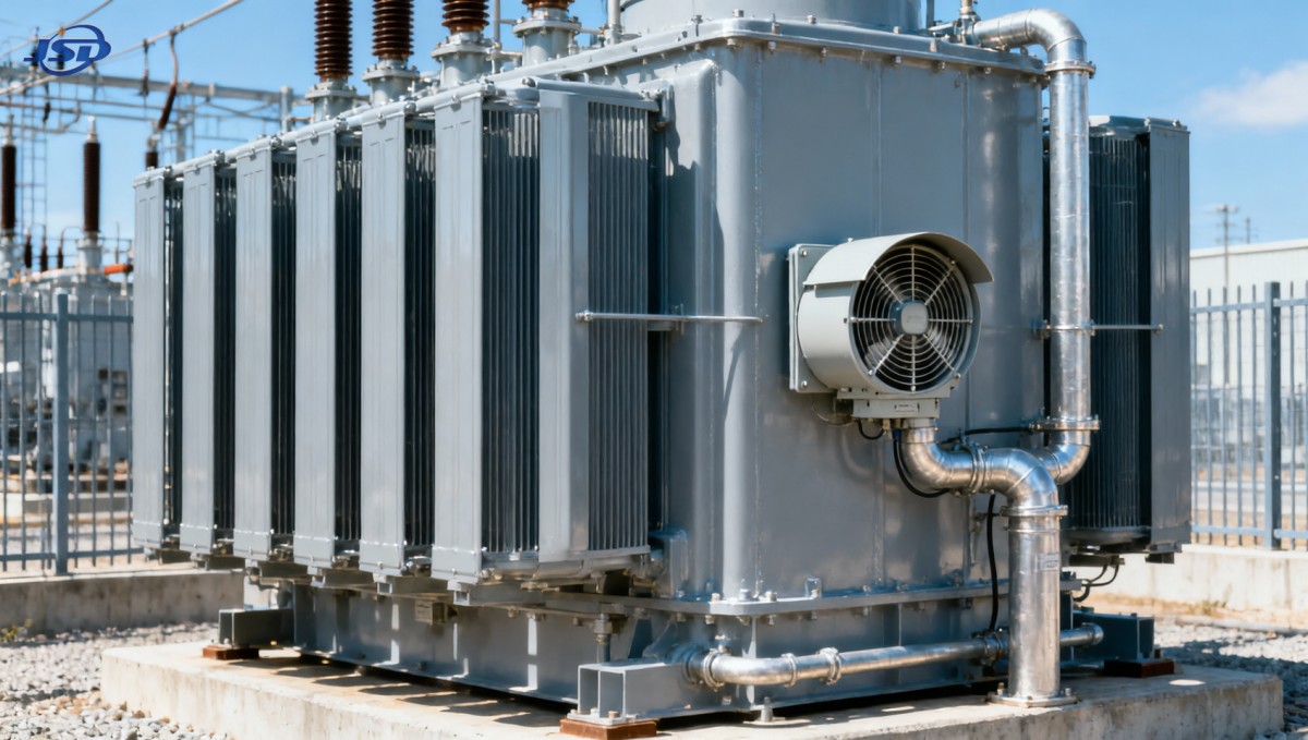
Cleaning, electrical inspection, and work near energized equipment require the appropriate isolation and site safety controls. Restoring the intended cooling conditions is preferable to assigning a permanent lower rating to an installation with correctable airflow restrictions.
Use hot-spot temperature—not top-oil temperature alone
Top-oil temperature is valuable because it indicates the overall thermal condition of the oil near the top of the transformer. It does not directly reveal the hottest part of the winding. The winding hot spot can reach a limiting temperature while the top-oil reading still appears acceptable.
The underlying relationship is:
Winding hot-spot temperature = local ambient temperature + top-oil rise above ambient + winding hot-spot rise above top oil.
Both temperature rises depend on load and transformer design. Top-oil response is relatively slow because of the thermal mass of the oil and tank. The winding temperature can respond more quickly to a load increase. Consequently, a satisfactory oil reading immediately after adding load does not prove that the new loading level is sustainable.
A winding temperature indicator may be a thermal image derived from oil temperature and a current-heated element rather than a direct winding measurement. Electronic systems may calculate hot-spot temperature, while some transformers have direct fiber-optic sensors. Know which method is installed, how it is calibrated, and whether its parameters match the transformer.
Trend information is more useful than an isolated reading. Record ambient temperature, top-oil temperature, winding temperature or estimated hot spot, phase currents, and loading over the same time period. Compare similar loads at similar ambient temperatures. An unexplained increase in temperature rise warrants investigation rather than an automatic adjustment to the alarm setting.
Convert the actual load into a thermal operating limit
The nameplate is expressed in kVA, not kW. For a balanced three-phase load:
S (kVA) = √3 × line voltage (V) × line current (A) ÷ 1000.
At 400 V, 1500 kVA corresponds to approximately 2165 A. At 415 V, it corresponds to approximately 2087 A. These figures describe rated current at those voltages; they do not establish the current that is thermally acceptable during hot weather. Use the actual rated secondary voltage and check each phase rather than relying only on a combined demand display.
A load of 1200 kW at a power factor of 0.8 is already 1500 kVA. Reducing kW without checking power factor may therefore produce less thermal relief than expected. Likewise, phase imbalance can overheat one winding even when total apparent power remains below the nameplate rating.
For a predominantly sinusoidal load, winding resistive losses approximately follow the square of current. Reducing current to 90% of rated current reduces that component to about 81% of its rated-current value, assuming unchanged resistance. Total transformer losses do not fall by the same percentage: core losses remain largely present at the same voltage and frequency, and winding resistance changes with temperature.
This explains why load reduction can provide substantial cooling relief, but it does not justify a universal derating percentage. Two 1500 kVA units with different loss characteristics, radiator arrangements, or hot-spot factors can require different limits at the same ambient temperature.
An illustrative temperature-budget check
Suppose an approved thermal assessment predicts a 110°C winding hot spot at a 30°C ambient temperature for a particular steady load. If the cooling-air temperature rises to 45°C and the temperature rises above ambient remain approximately unchanged, the hot spot would approach 125°C.
These numbers are illustrative, not recommended operating limits. The point is that hotter air consumes thermal margin even without a load increase. The actual response also depends on changing losses and heat transfer. If the applicable operating limit remains unchanged, the load must be reduced enough to lower the combined oil and winding rises. The required reduction should come from a validated thermal model or manufacturer loading curve, not from subtracting the ambient increase from the kVA rating.
Account for yesterday’s load and tonight’s recovery
A transformer that has carried high load for several hours enters the afternoon heat peak with stored thermal energy. The same instantaneous load may produce a different temperature trajectory after a lightly loaded night. This is why a time-dependent loading assessment is more useful than a calculation based only on the highest air temperature.
Use an operating profile that includes the previous load, the expected ambient-temperature curve, planned load changes, and the duration of each loading period. A suitable model estimates top-oil and winding hot-spot temperatures over time and assesses insulation aging against the agreed operating criteria.
Short-duration loading and continuous loading are different decisions. A brief peak may be acceptable under an approved loading assessment, yet the same load repeated throughout a hot shift may produce excessive temperature or accumulated aging. Cooler nighttime air provides recovery only if loading and ventilation allow the transformer to lose the stored heat.
Where detailed thermal data are unavailable, obtain a written hot-weather loading recommendation from the manufacturer. Until then, use a conservative site-approved operating envelope based on the available temperature evidence, equipment condition, and protection requirements. The absence of an alarm is not evidence that insulation aging is acceptable.
Rectifier and nonlinear loads need a separate check
Loads supplied through rectifiers, drives, and other power-electronic equipment can introduce harmonic currents. These increase losses in ways that are not fully represented by a simple fundamental-frequency kVA calculation. RMS current remains important, but winding eddy losses and stray losses also depend on the harmonic spectrum and transformer construction.
A general-purpose distribution transformer should not be assumed to have the same thermal capability as a transformer designed for a specified rectifier duty. For equipment such as the Isolation and Rectifier Special Transformer, available in configurations including ONAN cooling, the relevant question is whether the particular unit’s rating covers the actual converter arrangement, harmonic currents, and site ambient conditions. The product category alone does not establish a hot-weather overload allowance.
When nonlinear loads are significant, provide the manufacturer with measured harmonic data, RMS phase currents, converter operating details, and the daily duty cycle. Copper windings or a stated overload capability do not remove the need for that assessment.
Turn the assessment into workable operating actions
A hot-weather operating limit should identify an allowable load, its duration, the ambient conditions under which it applies, and the temperature conditions that require intervention. A single reduced kVA number without these boundaries can be misleading.
Where load reduction is required, shift or shed nonessential demand, stagger high-current processes, and avoid combining a large load increase with the hottest part of the day. Verify feeder, busbar, cable, and switchgear limits before transferring demand to another circuit.
Do not raise alarm or trip settings merely to maintain production. Nor should temporary fans be treated as an automatic capacity upgrade. Engineered forced-air cooling may improve heat rejection, but a higher rating requires confirmation that the transformer design, accessories, protection, and installation support it.
The practical limit for a 1500 kVA ONAN transformer is the load it can carry within its approved temperature, aging, and equipment constraints under the actual site conditions. A reliable operating decision therefore ties together local cooling-air temperature, measured current, winding thermal behavior, and load duration. That combination—not an arbitrary seasonal percentage—provides a sound basis for maintaining supply without consuming insulation life unknowingly.

Get a Quote
Regardless of whether you require general advice or specific support, we are happy to help you.
Send Us Your Inquiry Today

Jinshida Electric remains committed to contributing to global energy development through professional manufacturing and superior service.