





Pad-Mounted Transformer Site Planning: Access, Drainage, and Clearances
Pad-Mounted Transformer Site Planning: Access, Drainage, and Clearances
A pad mounted transformer can support reliable power distribution only when its location is planned as carefully as its electrical specifications. Overlooked access routes, inadequate drainage, or insufficient clearances can lead to redesigns, inspection delays, and costly maintenance constraints. Effective site planning starts with coordinating utility requirements, applicable codes, equipment dimensions, and local ground conditions before the foundation is finalized.
The practical challenge is that several teams influence the same space. Electrical engineers need workable cable routes. Civil engineers manage levels and runoff. Architects want equipment screened from view. Operators need doors to open and maintenance vehicles to reach the unit. A location that works on one drawing may fail when these requirements are overlaid.
Resolve the site constraints before freezing the foundation
Start by confirming who owns the transformer and who approves its location. Utility-owned equipment may be subject to utility construction standards, access easements, and approved installation arrangements. Customer-owned equipment still needs coordination with the relevant electrical, building, fire, and environmental authorities. Manufacturer instructions add another layer; they do not replace local requirements.
For US projects, applicable NEC provisions and utility standards may both affect the layout. Other markets use their own adopted electrical and building rules. There is no single clearance figure that can safely be applied to every pad-mounted installation. Voltage, compartment configuration, insulating liquid, adjacent construction, and jurisdiction all matter.
Before issuing the foundation for construction, obtain a coordinated equipment drawing showing:
- Overall dimensions, operating weight, support requirements, and lifting provisions.
- Door orientation, full opening envelope, and access to serviceable components.
- Cable entry openings, termination positions, and required cable bending space.
- Cooling surfaces, grounding connections, and any auxiliary equipment.
- Manufacturer installation requirements and the utility’s approved site arrangement.
A preliminary footprint is useful for reserving space, but it is not a reliable basis for final concrete work. Changes in cable compartments, cooling arrangements, or connection layout can affect the pad and surrounding working area even when the rated capacity remains unchanged.
Plan access for replacement, not just delivery
Getting a transformer onto its pad during construction is often easier than removing it after the site is occupied. Temporary roads disappear. Fences are completed. Parking spaces fill up. Landscaping grows into the route that originally looked clear.
Test the permanent layout against three separate activities: routine inspection, component maintenance, and complete replacement. Personnel access may be adequate for inspection but insufficient for a service truck, crane, or lifting operation. The replacement plan should identify a suitable vehicle position, lifting reach, overhead restrictions, and a route capable of supporting the anticipated loads.
Crane access deserves particular attention. A nearby paved surface is not automatically suitable for outriggers. Underground utilities, chambers, recently backfilled trenches, and weak ground can restrict setup. Have the lifting contractor and civil team review the proposed position using the actual equipment weight and lifting geometry.
At the cabinet, doors must open to their required position without striking bollards, fences, or retaining walls. Operators also need room for the tools and procedures associated with the selected switchgear and terminations. Keep this service zone out of parking bays, material storage areas, and pedestrian shortcuts.
Security and accessibility should be designed together. Locked gates and protective barriers may be necessary, but authorized personnel need a dependable way to enter. If removal of a fence panel is part of the replacement strategy, record that arrangement rather than leaving it as an informal assumption.
Drainage starts outside the pad
An outdoor enclosure is not a substitute for flood protection. Surface water can collect around the base, enter cable spaces, erode supporting ground, or make the working area unsafe. Raising the concrete pad may help, but only when surrounding grades and water flow paths are addressed as well.
Review finished ground levels, upstream runoff, roof drainage, nearby channels, and the effects of future paving. Avoid placing the transformer at a local low point simply because that area is otherwise unused. A site visit during or after rainfall can reveal drainage behavior that a contour drawing does not fully explain.
The intended arrangement is a stable, level equipment support with surrounding surfaces directing water away, without creating awkward steps or excessive slopes in the operating area. Pad elevation should follow the project’s drainage and flood assessment, utility details, and manufacturer requirements—not an arbitrary standard height.
Cable trenches and conduits need their own water-management details. They can carry groundwater or runoff toward equipment even when the surface looks dry. Coordinate approved sealing, drainage, and water-blocking measures with the cable installation design. Do not treat foam or improvised filling as an engineering solution.
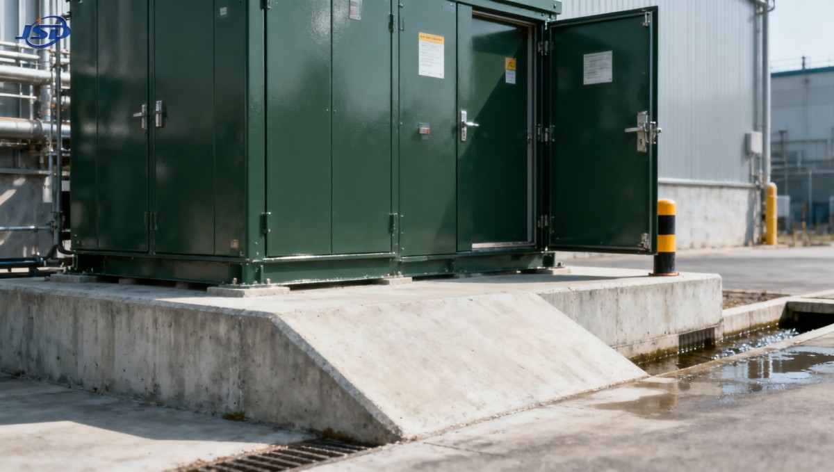
A coordinated plan-and-section drawing is useful here: show the cabinet opening direction, service zone, pad elevation, surrounding grades, cable entries, and runoff arrows together. Separating these details across unrelated drawings makes conflicts harder to spot.
For liquid-filled transformers, stormwater management must also be coordinated with any required spill containment. The need for containment depends on the installation, liquid type and volume, environmental exposure, and local rules. A containment area must not simply collect rainwater indefinitely or discharge insulating liquid through an uncontrolled drain.
Clearances serve different purposes
“Transformer clearance” is often treated as one dimension around the enclosure. In practice, several boundaries may apply, and they are not interchangeable.
Working space and door movement
Electrical working space supports safe access to equipment that may require examination, adjustment, or servicing. Its dimensions depend on applicable rules and installation conditions. Door swing is a separate geometric requirement. A door that opens does not prove that the working space is sufficient, and compliant working space may still be obstructed by a poorly positioned barrier.
Cooling and building separation
Cooling clearances protect airflow around the enclosure, radiators, or fans. Decorative screens and closely planted shrubs can compromise that airflow while leaving the front doors accessible. Any screen should be reviewed against the actual cooling arrangement, especially where forced-air cooling is specified.
Separation from buildings, openings, combustible materials, and escape routes addresses different risks. Requirements may depend on insulating liquid, construction type, fire protection measures, and utility rules. A fire-resistant barrier can be part of an approved design in some situations, but it is not a universal workaround for a constrained site.
Vehicle protection without blocking operation
Where vehicles could strike the equipment, evaluate bollards or other protective measures. Locate them outside required door and working envelopes, and check their foundations against cable ducts and grounding conductors. Removable barriers may assist replacement access, provided their design and operating arrangements are accepted by the responsible parties.
Put every applicable boundary on the site drawing. A single note saying “maintain required clearance” leaves too much interpretation to construction crews and future site operators.
Renewable-energy sites need equipment-specific checks
Wind-energy projects add constraints such as remote access roads, exposed terrain, long cable routes, and potentially corrosive coastal conditions. A turbine step-up transformer may be outdoor-installed, but that does not automatically establish a pad-mounted cabinet configuration or a particular service-access arrangement.
Jinshida Electric Power Technology Co., Ltd.’s Transformer for Wind Power Generation illustrates why the selected configuration matters. Its supplied specifications include 630–5000 kVA ratings, 0.69 kV low voltage, 10/20/35 kV high-voltage options, copper windings, and ONAN/ONAF cooling options. For site planning, confirm the dimensions, mass, cooling equipment, and connection arrangement of the exact offered unit rather than extrapolating from this rating range.
The stated IEC 60076 standard concerns transformer requirements; it does not, by itself, establish local site clearances, flood suitability, or approval for a particular installation. Coastal or offshore applications also require project-specific confirmation of environmental protection and installation conditions.
Jinshida’s work across power-equipment R&D, manufacturing, and application provides a basis for discussing these equipment interfaces. The useful supplier input is concrete: approved drawings, installation limits, maintenance access requirements, and configuration-specific technical documentation. Those details connect product selection to civil design more effectively than general claims about reliability.
Use a coordinated release check before concrete is poured
Before releasing the pad for construction, bring the electrical designer, civil engineer, utility representative where relevant, equipment supplier, and future operator into one layout review. Resolve disagreements while the solution can still be moved on a drawing.
- Confirm that the equipment drawing revision matches the foundation and cable-entry drawings.
- Verify bearing conditions, foundation design, and the effect of adjacent trenches.
- Check drainage paths and pad levels against the finished site, not temporary construction grades.
- Record the source and approval status of each required clearance.
- Demonstrate a workable replacement route, including gates, lifting positions, and overhead obstacles.
- Assign responsibility for keeping access and working areas clear after handover.
Repeat the physical check before energization. Final landscaping, paving, fences, and parking controls can invalidate an otherwise sound design. The decisive question is not merely whether the pad mounted transformer fits: it is whether the completed site allows it to be operated, maintained, and eventually replaced without rebuilding the surrounding infrastructure.

Get a Quote
Regardless of whether you require general advice or specific support, we are happy to help you.
Send Us Your Inquiry Today

Jinshida Electric remains committed to contributing to global energy development through professional manufacturing and superior service.