





Oil-Cooled Substation Transformers: Maintenance Checks That Prevent Failures
A developing transformer fault rarely begins with a dramatic alarm. More often, the first evidence is a small change: an oil level that no longer matches temperature, a radiator bank that stays cooler than the others, a gas relay that operates intermittently, or a dissolved-gas result that no longer follows its earlier pattern. Preventing failure starts with treating these changes as connected evidence rather than isolated defects.
For an oil cooled substation transformer, the maintenance objective is to preserve three linked conditions: clean and dry insulating oil, sound cellulose insulation, and reliable heat removal. A defect in any one of these areas can accelerate damage in the others. Water lowers dielectric strength and speeds paper aging; overheating creates gases and oxidizes oil; oil leaks invite moisture entry and reduce cooling margin.
Start With Operating Evidence Before Opening Anything
Review the loading profile, ambient temperature, top-oil temperature, winding temperature indication where available, cooling stage status, previous oil-test results, relay records, and work history before a field inspection. A temperature increase has a different meaning during a sustained load rise than during unchanged loading. Likewise, a higher oil level on a cold day is not automatically a problem, while a continuing level decline under similar temperature conditions deserves attention.
Trend information is more valuable than one reading. Compare present values with the transformer's own earlier records, especially after a tap-changer service event, a cooling-system repair, a through-fault, or extended high-load operation. Nameplate rating alone does not establish whether the thermal condition is normal. Site ventilation, solar exposure, radiator fouling, fan availability, oil circulation, and actual phase loading all influence the result.
Record abnormalities precisely. “Oil leak at tank” is too broad to guide repair. Identify whether oil is present at a flange gasket, valve spindle, bushing turret, radiator connection, pressure-relief device, conservator pipe, cable box, or tap-changer compartment. Note whether the surface is fresh and wet, dusty with old oil residue, or newly disturbed after maintenance. That distinction prevents a minor seepage from being confused with an active loss of insulation oil.
Oil Condition: Look Beyond Color
Dark oil may indicate oxidation, but color alone cannot determine oil health. Oil darkens for several reasons, including long service, suspended particles, metal wear products, carbon from an internal fault, or contamination introduced during handling. Sample quality is equally important. A sample taken from a poorly flushed valve can contain sediment or moisture that does not represent the bulk oil.
Use a clean, compatible sampling container and follow the site sampling procedure. Before drawing the sample, examine the drain valve for leakage, corrosion, damaged threads, and evidence that the cap or seal has been left loose. Flush the dead volume where the procedure permits. Label the sample with transformer identity, compartment, operating temperature, load condition, and the time of collection. Oil from the main tank and oil from an on-load tap changer must never be mixed in interpretation because their gas and contamination patterns can differ substantially.
Laboratory results become useful when they are read together. Moisture content is affected by oil temperature and by the equilibrium between oil and paper insulation. A single low oil-moisture result does not prove that the cellulose is dry, particularly after temperature changes have shifted moisture into the paper. Dielectric breakdown strength may fall because of water, particles, fibers, or poor sampling practice. Acidity, interfacial tension, inhibitor condition, and sludge tendency reveal oil aging from different angles; no single test replaces the others.
Dissolved gas analysis deserves prompt follow-up when a gas concentration changes sharply, a previously stable pattern begins to rise, or several gases evolve together in a way that does not match normal loading. Gas generation can result from overheating, partial discharge, arcing, or tap-changer activity. The location matters. Before assigning a main-tank fault, confirm the sampled compartment, inspect recent switching history, and consider whether a communication or sampling error explains the apparent change. Re-sampling is often justified when a result conflicts with the transformer’s condition indicators.
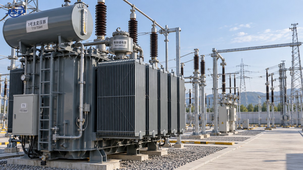
Moisture Entry Often Begins at a Small External Defect
The conservator breather is an early barrier against atmospheric moisture. Check the dehydrating medium for loss of active color or physical deterioration, inspect the oil seal where fitted, and make sure the air path is not blocked. A blocked breather can produce pressure differences that stress seals; an exhausted breather permits damp air to enter during thermal breathing. These conditions may exist without an obvious oil leak.
Examine gaskets and bolted joints with the transformer temperature in mind. Rubber components harden with age, while gasket compression can change after thermal cycling. Tightening bolts without a controlled pattern may distort a cover, extrude a gasket, or create a new leak beside the original one. For a persistent flange leak, confirm flatness, gasket condition, bolt condition, and correct assembly before increasing torque.
Bushing interfaces need close attention because they combine electrical stress, weather exposure, and mechanical loading from conductors. Oil staining around a bushing flange can be a seal issue, but contamination tracking on the external porcelain or composite surface points to a different risk. Inspect for cracks, chips, loose hardware, damaged grading rings, and conductor movement. A hot connection may create discoloration without a bushing insulation defect, so infrared findings should be checked against load current, phase balance, emissivity assumptions, and a direct inspection during an outage.
Separate Cooling Faults From Internal Heating
High top-oil temperature is frequently blamed on overload, yet restricted cooling is a common contributor. Inspect radiator fins for mud, vegetation, paint buildup, or damage that limits heat transfer. A radiator valve left partially closed after transport or service can cause one section to remain unexpectedly cool. Confirm the valve positions physically rather than relying on an old checklist or a painted indicator.
For forced cooling systems, verify that fan rotation, airflow direction, motor current, controls, and automatic staging are correct. A fan that turns is not necessarily moving useful air; reversed rotation or an obstructed guard can sharply reduce airflow. Check pumps for vibration, leakage, unusual noise, and loss of circulation where oil-forced cooling is installed. Compare inlet and outlet temperatures across cooling banks when safe methods are available. A uniform temperature pattern on a heavily loaded unit may point to broad thermal stress, whereas one inactive bank suggests a local circulation or control issue.
Temperature instruments and alarm contacts require their own verification. A failed sensor can conceal overheating, while a poorly calibrated indicator can trigger unnecessary response. Compare installed indicators with a suitable reference method during planned work, and test alarm, trip, fan-start, and remote-status circuits through the full signal path. Do not bypass a temperature trip merely because an indicator appears suspect; first establish a controlled protection arrangement.
Insulation Tests Need Context
Insulation resistance and polarization measurements are most useful when compared with prior tests made under similar conditions. Temperature, surface contamination, test voltage, duration, and winding condition affect results. A lower insulation-resistance value after humid weather may reflect external bushing contamination rather than an internal winding defect. Conversely, a satisfactory resistance value does not rule out localized winding deformation, a weak lead connection, or an evolving turn-to-turn problem.
Before an outage test, ensure that the transformer is isolated, discharged, properly grounded, and separated from connected cables, surge arresters, voltage transformers, and other equipment that could distort results or be damaged by the test. Record all connections removed and restore them through a documented sequence. Incorrect reconnection after a well-executed test can create a failure more immediate than the condition being investigated.
Where baseline data and approved procedures are available, winding resistance, turns-ratio, excitation-current, and frequency-response methods can help distinguish winding, core, lead, and tap-position concerns. These methods should be chosen to answer a specific question. Testing every available parameter after every minor abnormality can produce conflicting results without improving the diagnosis. After a severe external fault, however, electrical comparison tests may be justified even when no oil leak or visible damage is present, because winding displacement can remain hidden.
Protective Devices Must Be Treated as Active Equipment
A Buchholz relay, sudden-pressure relay, pressure-relief device, oil-level indicator, and temperature-protection circuit are not passive accessories. Inspect their mechanical condition, electrical contacts, wiring terminations, and annunciation path. A relay flag that was reset without investigation can erase valuable fault evidence. When a gas-operated relay has alarmed, preserve gas for examination where site procedures allow, verify oil level and relay condition, and correlate the event with dissolved-gas data and operating records before returning the unit to normal loading.
Pressure-relief devices require particular care after operation. Inspect for an operated indicator, oil discharge, damaged seals, and any blockage around the outlet. Replacing or resetting the device addresses only the visible result. The cause of pressure rise still needs examination, especially when there is evidence of internal arcing, abnormal gas production, or a recent short-circuit event.
Tap Changers and Connections Need a Separate Review
Tap changers introduce wear, contact erosion, and oil contamination mechanisms that differ from those of the main transformer tank. Confirm the actual tap position against control indication and system voltage requirements. A mismatch can cause sustained overvoltage or undervoltage even when the transformer itself is healthy. Inspect the drive mechanism, interlocks, counters, cabinet heater, and terminal tightness. Repeated hunting between positions often points to control settings, sensing problems, or unstable system conditions rather than a mechanical defect alone.
During a planned outage, inspect accessible bolted electrical joints for heating marks, loss of spring pressure, oxidation, and conductor strain. Torque values must follow the applicable equipment documentation; indiscriminate tightening can damage threads or deform connection hardware. Any repaired connection should be rechecked under load with temperature monitoring where practical.
When Oil Equipment Is the Wrong Fit
Some recurring maintenance findings arise from the installation environment rather than poor execution. Indoor spaces with difficult oil containment, restricted ventilation, or heightened fire constraints may justify evaluating a dry-type alternative during replacement planning. A 11kV Three-Phase Cast Resin Dry-Type Distribution Transformer uses cast-resin insulation rather than insulating oil and is intended for distribution applications such as urban networks and building or industrial power systems. That change removes oil leakage and oil-sampling tasks, but it does not eliminate maintenance: ventilation paths, coil cleanliness, temperature protection, connections, and enclosure condition still require inspection.
For an existing oil-filled unit, the practical response to abnormal evidence is disciplined escalation. Stabilize loading where needed, protect the asset from further stress, collect repeatable data, and repair the verified cause rather than the most visible symptom. This approach limits unnecessary outages while ensuring that small defects do not remain in service long enough to become internal failures.

Get a Quote
Regardless of whether you require general advice or specific support, we are happy to help you.
Send Us Your Inquiry Today

Jinshida Electric remains committed to contributing to global energy development through professional manufacturing and superior service.