





Oil-Cooled Substation Power Transformers: What Affects Thermal Performance?
Oil-Cooled Substation Power Transformers: What Affects Thermal Performance?
The thermal performance of an oil cooled substation power transformer directly influences reliability, loading capacity, insulation life, and operating cost. For technical evaluators, understanding how oil circulation, cooling system design, ambient conditions, load profile, and material quality affect heat dissipation is essential when comparing transformer solutions. This article examines the key thermal factors that determine stable, efficient operation in modern substations and demanding power distribution applications.
A transformer does not fail simply because its average temperature is high. The more serious concern is often a local hot spot in a winding, lead connection, tap-changer area, or restricted oil channel. Those locations may experience substantially higher temperatures than the top-oil indication suggests. A sound thermal assessment therefore looks beyond the nameplate cooling designation and asks whether the complete design can remove internally generated heat under the actual duty cycle and site conditions.
Heat Generation Starts with Losses
Thermal behavior begins with loss. Core loss is present whenever the transformer is energized and is mainly influenced by core steel quality, flux density, frequency, manufacturing accuracy, and magnetic joint construction. Load loss rises approximately with the square of current and includes winding resistance loss, stray loss caused by leakage flux, and losses in structural metal parts. At high loading, load loss usually becomes the dominant thermal driver.
This distinction matters when reviewing a specification. A transformer serving a lightly loaded but continuously energized substation may benefit most from low no-load loss. A unit exposed to prolonged heavy industrial demand, renewable-energy export peaks, or seasonal overloads requires particular scrutiny of load loss, winding temperature rise, and cooling margin. Selecting only on rated kVA can conceal this difference.
Conductor selection and winding geometry also matter. Copper and aluminum can both be used successfully when the design is engineered correctly, but conductor cross-section, transposition, joint quality, insulation spacing, and the path available for oil flow all affect resistance and hot-spot control. Excessive eddy-current loss in conductors or metallic clamping components may not be obvious from a basic loss summary, yet it can become significant in transformers with high current, non-sinusoidal loading, or demanding short-circuit duties.
Oil Is Both Insulation and a Heat-Transfer Medium
In an oil cooled substation power transformer, insulating liquid performs two linked tasks: it provides dielectric insulation and transports heat from the active part to the tank walls and radiators. Its effectiveness depends not only on the oil itself, but also on whether the internal flow path reaches the parts that need cooling most.
Natural oil circulation relies on density differences. Oil heated in the windings rises, cooler oil descends, and the circulation loop carries heat toward radiators or other external cooling surfaces. This is the principle behind ONAN cooling, commonly described as Oil Natural Air Natural. It is simple and dependable because it does not depend on pumps or fans, but its heat-removal capacity is limited by the available temperature difference and the physical layout of the cooling circuit.
Forced-air stages add fans to increase heat transfer from radiators to the surrounding air. Forced-oil arrangements use pumps to establish more controlled oil movement. These systems can increase usable loading capability, but they introduce auxiliary equipment, controls, maintenance needs, and failure modes. A rating that depends on fans or pumps should never be treated as identical to a self-cooled rating. Evaluators should confirm the available capacity at each cooling stage, the required automatic start logic, alarm points, and the operating consequence if one fan bank or pump becomes unavailable.
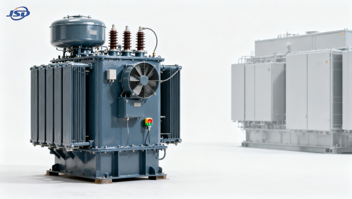
Oil condition is equally relevant. Moisture, oxidation products, particles, dissolved gases, and reduced dielectric strength are often discussed as insulation risks, but they can also affect thermal reliability indirectly. Sludge deposits can restrict cooling passages and radiator performance. Aging oil and paper insulation may accelerate where oxygen, elevated temperature, and moisture coexist. For an installed fleet, oil testing and temperature trends should be read together rather than as separate maintenance records.
Cooling Hardware Must Match the Site, Not Just the Drawing
Radiator area, tube geometry, tank design, fan capacity, pump head, and pipe routing collectively determine how efficiently heat leaves the transformer. A technically sound cooler can still underperform if radiators are crowded against a wall, exposed to recirculating hot exhaust air, blocked by debris, or installed in an enclosure with weak ventilation. This is especially relevant in compact substations, industrial sites, coastal facilities, and locations where dust accumulation is persistent.
Ambient temperature is not a minor installation detail. Transformer temperature-rise capability is assessed relative to an assumed ambient condition under the applicable standard and agreed specification. If the site experiences high summer temperatures, direct solar exposure, altitude-related changes in air density, or restricted air movement, the same electrical load will produce a different thermal outcome. The procurement team should state the maximum and average ambient conditions expected at the installation point rather than rely on a generic climate category.
Altitude deserves attention because thinner air reduces convective cooling. Projects at elevated locations may need derating or a cooling-system adjustment. Likewise, a transformer positioned near boilers, furnaces, compressor exhausts, or adjacent power equipment can face an effective ambient temperature well above the meteorological design value. These are site-engineering questions, not issues that can be solved after factory testing.
Load Shape Often Matters More Than a Single Load Figure
A transformer’s thermal state has inertia. It does not reach its highest oil and winding temperatures the moment current rises, nor does it cool instantly when load falls. For this reason, a daily or seasonal load curve is more useful than a statement that the transformer “normally runs at 80%.” A short peak after a long low-load period may be acceptable; the same peak sustained through a hot afternoon can produce a very different hot-spot temperature.
Harmonic currents add another layer. Nonlinear loads associated with variable-speed drives, rectifiers, data-processing equipment, arc furnaces, and some power-electronic renewable applications can increase eddy-current and stray losses. The thermal impact depends on the harmonic spectrum, winding design, conductor arrangement, and system conditions. It should be evaluated from measured or credible projected load data, not assumed from total kVA alone.
Emergency loading is another area where terminology needs discipline. Permissible overload depends on the transformer’s thermal model, insulation system, prior loading, ambient temperature, cooling availability, and the asset owner’s acceptable loss-of-life criteria. A general statement that a transformer can tolerate overload does not establish that it can do so for a particular duration or at a specific site. IEC loading guidance and the project’s governing requirements should be reviewed alongside the manufacturer’s thermal documentation.
Insulation Temperature Is the Long-Term Reliability Question
The winding hot spot is central because cellulose insulation ages faster as temperature rises. Exact aging behavior depends on insulation type, moisture content, oxygen exposure, and operating history, so it should not be reduced to a universal life formula. Still, the engineering principle is clear: repeated or sustained high hot-spot temperatures consume insulation life faster than stable operation within the intended thermal limits.
This is why temperature indicators, winding-temperature simulation or direct sensing arrangements, cooling controls, and alarm/trip settings should be considered as an integrated protection scheme. Top-oil temperature provides useful information but is not a complete proxy for winding condition. The control philosophy should identify what initiates fans and pumps, what produces an alarm, what triggers load shedding or trip action, and how failures of temperature sensors or cooling auxiliaries are detected.
For critical substations, monitoring may also include dissolved gas analysis, moisture indicators, load records, and thermal trend analysis. These tools do not replace design margin, but they can reveal a change in behavior: a cooling bank that is losing effectiveness, unexpected load growth, a control problem, or developing internal losses. The value lies in comparing trends against the transformer’s normal operating baseline.
What to Verify Against IEC and Project Requirements
IEC 60076 is widely used for power-transformer requirements, but it is a series of documents rather than a substitute for a project specification. The agreed technical schedule should establish rated power, voltage ratio, tap range, vector group, impedance, insulation levels, loss values, temperature-rise limits, cooling designation, sound requirements, and test obligations. Local grid codes, utility practices, and national standards may add further requirements.
For thermal review, the most useful questions are practical:
- What rated output is available in self-cooled operation, and what output depends on each forced-cooling stage?
- What ambient temperature, altitude, solar exposure, and enclosure ventilation assumptions were used?
- What are the guaranteed no-load and load losses at the specified reference conditions?
- How are winding hot spots assessed, and which temperature-rise tests are required?
- What redundancy, alarms, local controls, and remote status signals are required for fans and pumps?
- Will harmonic loading, frequent overloads, or unusual duty cycles require a dedicated thermal calculation?
Factory routine and type tests provide important evidence, but they cannot reproduce every installation condition. A successful evaluation connects tested performance with the actual substation layout and expected operating profile. This is particularly important when a project requests a compact footprint, high continuous loading, low acoustic output, and elevated ambient performance at the same time; these objectives can conflict and must be resolved explicitly.
When Oil Cooling Is Not the Only Thermal Strategy
Oil-immersed designs remain a practical choice for many outdoor substations and larger distribution applications because the liquid provides effective internal heat transfer. However, installation constraints can shift the decision toward dry-type equipment. Indoor substations in hospitals, commercial buildings, data centers, mining facilities, and some renewable-energy installations may prioritize fire behavior, space planning, or avoidance of oil-leakage risk.
In those circumstances, a comparison with a cast-resin alternative should focus on the whole installation, not simply transformer losses. The 33kV Cast Resin Dry-Type Distribution Transformer is designed for distribution duties from 33kV to 0.4kV, with capacities stated from 30 to 2500 kVA and forced-air overload capability subject to its specified conditions. Its epoxy-resin insulation system and F1 fire-performance classification address a different set of project constraints. It is not a direct replacement for every oil-cooled substation transformer, particularly where voltage class, capacity, outdoor exposure, or network duty differs, but it illustrates why cooling technology must be assessed alongside fire, maintenance, and siting requirements.
Thermal Performance Is Decided Before Commissioning
The strongest transformer thermal designs are not defined by a single large radiator bank or an ambitious overload statement. They result from a disciplined match between loss design, winding cooling ducts, oil circulation, external heat rejection, insulation capability, control logic, and real operating conditions. Weakness in any one of these areas can limit the useful margin of the whole unit.
Jinshida Electric Power Technology Co., Ltd. approaches transmission and distribution equipment through this wider engineering lens, combining technical development, controlled manufacturing processes, and quality management for grid, industrial, new-energy, and infrastructure applications. For a thermal review, the most productive next step is to provide the expected load curve, maximum ambient and altitude, harmonic profile where relevant, installation arrangement, required standards, and cooling-auxiliary philosophy. Those inputs allow the transformer design to be evaluated as an operating system rather than as a nameplate item.

Get a Quote
Regardless of whether you require general advice or specific support, we are happy to help you.
Send Us Your Inquiry Today

Jinshida Electric remains committed to contributing to global energy development through professional manufacturing and superior service.