





Mobile Compact Substation Transformers: Checks Before Each Relocation
A mobile compact substation transformer should leave its current site only when its electrical condition, transport arrangements, and destination requirements have been checked. Recommissioning requires a separate decision after arrival: equipment that was serviceable before loading may have suffered movement, moisture ingress, or connection damage during transport.
For operators, the practical approach is to establish two release points: permission to move and permission to energize. Each needs recorded checks and a responsible person. An unresolved oil leak, uncertain lifting arrangement, incompatible supply, or incomplete earthing system should hold the relocation at the relevant stage, even when the next site urgently needs power.
Confirm that the next site can accept the unit
Start with the destination while the substation is still connected at its existing location. Discovering a voltage mismatch or unsuitable foundation after delivery can leave both sites without the planned supply. Use the equipment nameplate, approved drawings, operating manual, and destination electrical design to establish compatibility.
Check the incoming voltage and frequency against the transformer rating and available tap positions. Confirm the required outgoing voltage, phase arrangement, neutral provision, and load characteristics. A matching kVA figure alone does not establish suitability: motor starting, fluctuating loads, ambient temperature, altitude, and ventilation can affect the usable capacity or require further engineering review.
The new supply also needs a protection review. Available fault current, upstream protection, downstream discrimination, and switchgear ratings may differ between sites. Settings that worked at the previous location should not be copied automatically. Any changes must be approved and recorded by the person responsible for the electrical design.
Before dispatch, resolve these physical requirements:
- Support and access: The foundation or parking area must support the complete operating mass and provide the level condition required by the manufacturer. Check unloading access and any trailer support or stabilizer requirements.
- Water and ventilation: Locate the unit where drainage, flood exposure, and airflow are suitable. Allow the specified clearances around cooling surfaces, doors, and ventilation openings.
- Cable routes: Confirm entry positions, cable lengths, bending space, termination compatibility, and protection against vehicle movement or excavation.
- Operating space: Provide access for switching, inspection, emergency response, and maintenance, together with the barriers or restricted access required for the installation.
Earthing deserves its own design check. Ground conditions and the connection to the destination earthing network affect fault performance and touch-voltage risk. Reusing an earth lead or installing the same number of electrodes as at the previous site does not demonstrate that the new arrangement is adequate.
Create a reliable condition record before isolation
Record the unit’s condition before dismantling connections or securing it for transport. Include the equipment identity, tap position, protection settings, relevant operating readings, and any existing defects. Photographs of bushings, cable compartments, cooling surfaces, mounting points, and accessories give the receiving team a useful comparison after arrival.
Review recent alarms, trips, unusual temperature readings, abnormal sound, and signs of overheating. If an unexplained protection operation occurred shortly before the move, relocation should not become a way of postponing investigation. The cause may still be present at the next site.
For liquid-filled transformers, inspect accessible areas for leakage, damaged seals, and the indicated liquid level where a gauge is fitted. Interpret the reading using the manufacturer’s instructions and temperature conditions. For dry-type equipment, inspect accessible insulation, supports, ventilation paths, and signs of contamination without entering energized compartments or disturbing protective barriers.
Separate observations into defects that prevent transport, defects that prevent energization, and items acceptable for monitoring under an approved plan. Cosmetic enclosure damage may have little electrical consequence, but deformation around a lifting attachment, damaged insulation, or evidence of internal movement needs a different response. Record who assessed each defect and what closes it.
Isolate every source before preparing for transport
Isolation must cover the complete substation package. Depending on its configuration, possible sources include the incoming feeder, outgoing circuits capable of backfeed, auxiliary supplies, batteries, and connected generation. Automatic transfer equipment and remote controls also need attention because they may initiate switching or restore a supply unexpectedly.
Authorized personnel should follow the site’s switching, lockout, proving-dead, discharge, and earthing procedures, using equipment suitable for the voltage involved. Switching off a breaker is insufficient evidence that every compartment and terminal is safe. The isolation boundary must be clear to everyone disconnecting cables or preparing the unit for movement.
Where the existing site needs temporary power during relocation, arrange that supply before the outage. An Open Type Diesel Generator Set, available in prime ratings from 50 kVA to 500 kVA with an optional ATS, may support selected temporary loads when its output and installation suit the site. Generator sizing, transfer arrangements, neutral and earthing treatment, and backfeed prevention require their own assessment. An optional ATS does not establish compatibility with the existing distribution system.
After isolation has been established, identify and label disconnected power, control, and earth connections. Protect cable ends against moisture and contamination, and secure them against movement. Keep termination hardware organized so that reassembly uses the specified parts. Coordinate removal of site earth connections with the approved isolation procedure and transport configuration.
Check the complete assembly for the journey
Transport inspection should cover the transformer, switchgear, distribution equipment, enclosure, and supporting structure. Compact packaging can conceal damage: a distorted door may indicate frame movement, and a loose cable support can place strain on a termination even when the transformer tank appears intact.
With access established safely, inspect for cracked bushings, damaged cable glands, loose supports, displaced components, corrosion at structural attachments, and evidence of water entry. Look for heat discoloration or damaged insulation around accessible connections. Check enclosure seals, locks, hinges, and compartment barriers. Avoid opening sealed equipment or disturbing internal assemblies without the required authorization and manufacturer guidance.
Connection checks should follow the equipment maintenance instructions. Blanket retightening can damage threads, terminals, or insulating parts. Where a torque check is required, use the specified value, method, and suitable calibrated tool; an old witness mark alone cannot prove that a joint remains sound.
Prepare accessories according to the transport instructions. Depending on the design, gauges, cooling components, conservators, detachable bushings, or other projections may require protection or removal. Apply specified shipping restraints and close openings appropriately. Do not assume that every unit travels fully assembled, upright, or in the same condition in which it operates.
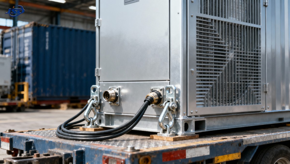
The lifting and securing plan must use the correct complete transport mass, center of gravity, designated lifting points, and specified lifting geometry. A lifting point on the transformer tank may be intended for the transformer alone, rather than the entire packaged substation. Doors, cooling pipes, cable supports, and convenient frame openings are not substitutes for approved attachments.
Check that tie-downs and their attachment points are suitable for the transport loads without deforming the enclosure or stressing accessories. Verify route restrictions, transport dimensions, trailer suitability, and the condition of any integral chassis. For trailer-mounted units, inspect the relevant coupling, running gear, brakes, and transport fittings under the applicable vehicle procedures.
Use arrival checks to decide the testing scope
On arrival, compare the assembly with its departure record before connecting cables. Inspect lifting points, supports, tie-down contact areas, bushings, seals, cooling components, and cable compartments. Look for fresh leakage, shifted parts, cracked insulation, loose hardware, and water or debris inside accessible compartments.
Transport incidents should be reported even when external damage is slight. A dropped load, severe impact, overturned package, or significant shock indication changes the assessment. If impact recorders were fitted, review them against the agreed limits. The absence of visible damage does not establish that internal connections and winding supports are unaffected.
Allow for any manufacturer-specified settling period or checks following transport, particularly for liquid-filled equipment. Verify that shipping restraints have been removed or changed to the operating configuration as instructed, accessories have been restored, and all compartments are ready for service.
The required electrical tests depend on the design, journey, maintenance history, and observed condition. Qualified personnel may need to verify insulation condition, winding resistance, transformation ratio, earth continuity, protection functions, or other specified characteristics. Tests should follow an approved commissioning procedure with defined methods and acceptance criteria.
For insulation testing, isolate or protect connected devices as required by their instructions. Electronic controls, surge protection, and other accessories may be damaged by an inappropriate test voltage. Interpret readings with temperature, moisture, previous results, and equipment design in mind; a single apparently satisfactory reading cannot clear every possible transport defect.
Where damage, leakage, or abnormal readings suggest an internal problem, hold energization for technical assessment. Additional liquid analysis or specialist testing may be appropriate for some units, but a routine move does not automatically justify every available test.
Release the installation for controlled energization
Before energization, verify the destination earthing arrangement, cable identification, terminations, phase sequence, tap position, and protection settings against the approved design. Confirm neutral connections and bonding arrangements explicitly. A missing neutral connection or unintended additional neutral-to-earth bond can create problems that a visual check of the main conductors will miss.
Complete the required functional checks on interlocks, trips, alarms, emergency controls, and auxiliary supplies. Confirm that ventilation paths are clear, doors and barriers are secured, tools and packing materials are removed, and temporary earths are accounted for under the switching procedure. Each check needs a result rather than a tick showing that someone visited the compartment.
Energize through the approved switching sequence, with the initial loading condition defined in advance. Observe indications from a safe operating position and check the outgoing supply before connecting loads as specified in the commissioning plan. Abnormal sound, smoke, leakage, unexpected protection operation, or unsuitable voltage requires a controlled stop and investigation.
As load is introduced, monitor current balance, voltage, temperature indications, and alarms. Early follow-up inspection can reveal heating at a reassembled connection or inadequate cooling at the new location. Where thermal inspection is used, interpret it under suitable loading conditions and compare like components; a cool connection under light load offers limited evidence about its behavior at higher current.
The relocation record should leave the receiving operator with a clear starting point: equipment identity, departure and arrival condition, test results, final settings, closed defects, and any approved monitoring requirements. Release the unit for service when those records support the decision and the responsible personnel have signed off. If an unexplained defect remains, keep the hold in place until there is a defensible reason to remove it.

Get a Quote
Regardless of whether you require general advice or specific support, we are happy to help you.
Send Us Your Inquiry Today

Jinshida Electric remains committed to contributing to global energy development through professional manufacturing and superior service.