





Medium Voltage Transformers for Solar Farms: Choosing Collector-Side Voltage Ratings
The collector-side voltage should be selected from the point of interconnection backward, not from the transformer catalog forward. A solar farm may use 20 kV, 33 kV, 34.5 kV, or another medium-voltage level across its collector network, but the correct choice is the one that matches the utility-approved interconnection architecture, the required equipment insulation class, the inverter block configuration, and the economic break point between cable losses and equipment cost.
A higher collector voltage does not automatically produce a better project. It reduces current for a given power transfer and can reduce feeder losses, yet it may require more expensive switchgear, cables, terminations, surge arresters, and transformer insulation. A lower voltage can simplify equipment selection for compact sites, but becomes difficult to justify when long feeder runs or large aggregated block capacity drive current and voltage drop upward. The practical decision is therefore a system-level electrical and construction decision, not simply a transformer rating decision.
Start with the utility voltage plan, not nominal labels alone
The first constraint is the voltage arrangement accepted by the network operator. The collector system must interface correctly with the project substation, protection scheme, metering arrangement, and grid-side step-up transformer. If the substation low-voltage winding is specified at 33 kV, for example, selecting 20 kV collector transformers because they are available locally introduces an unnecessary transformation stage or forces a redesign of the substation interface. Either outcome adds losses, equipment, controls, land requirements, and coordination risk.
Nominal voltage is only one part of the requirement. Specifications should distinguish among:
- the nominal operating voltage of the collector system;
- the highest voltage for equipment, which determines insulation coordination;
- the applicable frequency and system grounding method;
- continuous overvoltage conditions and fault-clearing assumptions;
- the required lightning impulse and power-frequency withstand levels;
- utility rules for protection, metering, reactive-power control, and voltage regulation.
A transformer marked for a nominal 33 kV system is not necessarily interchangeable with equipment designed around a different maximum system voltage. Cable accessories, bushings, separable connectors, switchgear, arresters, and clearances must all be suitable for the same insulation class. This issue is especially important in cross-border procurement, where a quotation may use a regional nominal-voltage convention that does not fully describe the required equipment rating.
Match the transformer ratio to the inverter block architecture
Collector transformers in solar farms normally raise inverter output voltage to the medium-voltage collection level. Their low-voltage winding must match the actual inverter output and operating tolerance, rather than a generic distribution voltage. Depending on the inverter design and regional electrical practice, the transformer LV side may be based on a 400 V, 415 V, 480 V, 690 V, or another specified inverter output level.
The ratio must also allow for the fact that an inverter does not behave like a passive load. Its output voltage, reactive-power duty, harmonic performance, and current limit are controlled operating characteristics. The selected transformer impedance and tap arrangement affect whether the inverter can maintain the voltage target at its terminals while delivering active power and required reactive power at the point of interconnection.
A ratio that appears correct under nominal conditions can become restrictive if it leaves insufficient voltage margin for:
- collector feeder voltage drop during high production;
- reactive-power export or absorption required by the grid code;
- transformer impedance voltage drop;
- inverter voltage limits under high ambient temperature;
- tap position and expected utility voltage variation.
For this reason, the collector transformer ratio should be checked using load-flow cases rather than selected solely by comparing nameplate voltages. At a minimum, the electrical model should examine maximum active export, high reactive-power demand, minimum and maximum grid voltage, one inverter block unavailable, and the intended operating position of taps.
Voltage choice changes feeder economics
For a three-phase collector feeder, current is approximately determined by:
I = P / (√3 × V × power factor)
As collector voltage increases, current decreases for the same transferred power. Lower current can reduce conductor size, resistive losses, voltage drop, and the number of parallel cable runs. This benefit becomes more material as feeder distances and block aggregation increase.
However, the comparison cannot stop at conductor losses. Medium-voltage cable pricing is influenced by conductor area, insulation voltage class, metallic screen design, installation method, jointing requirements, and local availability. Higher-voltage systems also require compatible switchgear and terminations, while testing and commissioning procedures may become more demanding. In a compact solar site with short collector runs, the loss reduction from a higher voltage may not offset these added costs. In a dispersed site with long radial feeders, the same voltage change can substantially improve the electrical layout.
A useful evaluation compares complete alternatives rather than isolated equipment prices. Each option should include transformer losses, feeder losses, cable trenching and installation, RMUs or sectionalizing points, switchgear ratings, civil works, spare-part strategy, commissioning scope, and projected energy value over the operating life. The relevant question is not whether a 33 kV cable is more expensive than a 20 kV cable; it is whether the complete 33 kV collection scheme delivers lower lifecycle cost for the approved site layout.
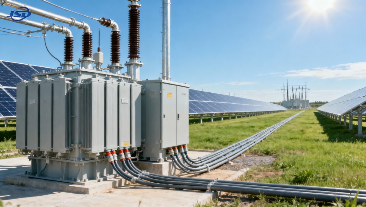
Transformer impedance is a design variable, not a boilerplate number
Transformer impedance affects fault current, voltage regulation, parallel operation, and inverter performance. A lower impedance reduces voltage drop across the transformer, which can improve inverter terminal voltage during high export. It also increases prospective short-circuit current on the LV side. A higher impedance helps limit fault duty but can consume voltage margin and complicate reactive-power performance.
The selected impedance must work with the inverter’s fault-current contribution, LV switchboard withstand rating, MV protection coordination, and the utility’s requirements for fault studies. Solar inverters typically provide controlled and limited fault current compared with synchronous generators, but this does not eliminate the need for a proper protection study. Transformer impedance, collector cable impedance, grounding design, protection settings, and inverter ride-through functions all influence fault detection and isolation.
It is risky to copy impedance values from a conventional industrial distribution transformer specification without confirming the solar plant’s network model. The inverter block, the feeder, and the substation protection philosophy form one electrical system.
Tap arrangements must support the operating strategy
Most collector transformers use de-energized taps rather than on-load tap changers. This is often appropriate because inverter controls can regulate reactive power dynamically and the collector voltage profile is usually designed around a fixed transformer ratio. Yet a fixed ratio is only satisfactory when the expected range of utility voltage and plant operating conditions has been assessed.
Tap selection should account for the voltage at the transformer HV terminals, expected feeder drop, inverter operating range, and the point at which reactive-power obligations are measured. A tap position that maximizes active-power output in one grid-voltage condition may reduce reactive-power headroom in another.
On-load tap changing may be justified in specific collection or substation applications, but it adds mechanical complexity, controls integration, maintenance requirements, and failure modes. It should be selected because the voltage-regulation study shows a need, not because it appears to offer a universally superior solution.
Do not confuse collector transformers with station-service transformers
A solar farm contains more than one transformer duty. The inverter step-up transformer transfers generation from inverter voltage to the MV collector system. A station-service transformer supplies auxiliary loads such as SCADA equipment, lighting, cooling, security systems, control panels, battery chargers, and maintenance facilities. The two applications can have different ratios, loading profiles, protection requirements, and environmental priorities.
For sites with a 20 kV auxiliary supply requirement, a 20kV/0.4kV Oil-Immersed Power Distribution Transformer may be relevant for station-service distribution rather than for the main inverter step-up duty. Its 20 kV to 0.4/0.415 kV ratio illustrates why transformer duty must be clearly separated during specification: a transformer selected to serve auxiliary LV loads is not a substitute for a collector transformer intended to raise inverter output to medium voltage.
This distinction matters in bid documentation. If the term “solar transformer” is used without defining the voltage sides and function, suppliers may quote technically valid but operationally unsuitable equipment. Each transformer schedule should state its service: inverter step-up, collector substation, grounding transformer, station service, or another defined role.
Environmental conditions influence voltage-rating reliability
Collector-side voltage selection also has physical installation consequences. Outdoor solar facilities may expose transformers and MV accessories to high ambient temperatures, intense solar radiation, dust, salt contamination, humidity, flooding risk, and limited access for maintenance. These conditions do not change the nominal voltage requirement, but they can influence insulation performance, cooling margins, enclosure selection, termination design, and the preferred transformer liquid or insulation system.
Oil-immersed transformers can offer robust thermal performance and are commonly considered where appropriate containment, fire-risk assessment, and environmental controls are incorporated into the design. Natural or ester-based insulating fluids may be evaluated where fire performance or environmental considerations are significant, but the decision should include local permitting requirements, spill containment arrangements, maintenance capability, and the manufacturer’s validated design limits.
Altitude requires particular attention. Reduced air density affects external insulation and cooling. A transformer, bushing, or switchgear assembly suitable at sea level may need derating or altered insulation clearances at elevated sites. The same principle applies to MV cable terminations and surge arresters. These details should be settled before equipment purchase orders are released, because site-specific changes after factory design approval can affect delivery schedules.
Specification discipline prevents late-stage compatibility problems
The most damaging collector-voltage errors tend to emerge at interfaces: an inverter transformer with an incompatible LV winding, MV switchgear with insufficient rating, cable connectors that do not match the bushing interface, or protection CT ratios that no longer work after a block-capacity revision. A coordinated equipment schedule is more valuable than a collection of individually compliant data sheets.
A technically complete transformer inquiry should define rated power under the relevant cooling condition, HV and LV rated voltages, tapping range and tap position, vector group, impedance tolerance, insulation levels, frequency, neutral treatment, losses, temperature-rise limits, terminal arrangement, cable-box or bushing interface, enclosure and corrosion requirements, applicable standards, routine and type-test expectations, transport constraints, and required documentation.
Standards such as IEC 60076 or the applicable IEEE C57 transformer standards can provide the technical framework, but they do not replace project-specific coordination. Utility interconnection conditions, local electrical codes, and insurer or lender technical requirements may impose additional requirements for testing, protection, fire safety, loss capitalization, and quality documentation.
The right rating is the one that preserves margin across the full plant model
A medium voltage transformer for solar farms should be selected after the collector voltage, inverter operating window, cable layout, impedance targets, fault levels, and substation interface have been evaluated together. The lowest initial-cost transformer can create hidden costs if its ratio limits inverter capability or if the selected voltage forces excessive feeder losses. Conversely, a higher-voltage collector system can be over-engineered when site geometry does not justify its additional equipment and installation cost.
The strongest basis for decision is a coordinated electrical study supported by an unambiguous equipment schedule. When the approved collector voltage is translated consistently into transformer insulation levels, tap settings, cable ratings, switchgear interfaces, and protection settings, the project avoids a class of late-stage changes that are expensive precisely because they appear to be minor nameplate details.

Get a Quote
Regardless of whether you require general advice or specific support, we are happy to help you.
Send Us Your Inquiry Today

Jinshida Electric remains committed to contributing to global energy development through professional manufacturing and superior service.