





Managing Inverter Harmonics With Medium Voltage Transformers in Solar Farms
Managing Inverter Harmonics With Medium Voltage Transformers in Solar Farms
Utility-scale solar plants are built around inverter blocks, and every inverter block introduces a power-quality question that cannot be left to the final commissioning stage. Modern inverters are highly efficient and normally include sophisticated switching control, but they do not produce a perfectly sinusoidal output. Their harmonic current, together with cable capacitance, capacitor banks, background grid distortion, and transformer impedance, can create operating conditions that look acceptable on a basic load-flow study yet become troublesome in the field.
For a technical evaluator, selecting a medium voltage transformer for solar farms is therefore not simply a matter of matching MVA rating, voltage ratio, and impedance. The transformer becomes part of the harmonic network. Its winding arrangement, thermal design, insulation system, loss assessment, tap range, and protection interfaces all influence whether the collector system remains stable through changing irradiance, inverter dispatch, and grid-voltage conditions.
The difficult part is that harmonics in solar applications are rarely caused by one component alone. A transformer may be blamed for overheating when the real issue is a resonance point created by the collector cables and a nearby reactive-power device. Conversely, an inverter supplier may show compliant output at its terminals while the plant-level voltage distortion rises at the point of interconnection. A useful transformer decision begins with looking at the complete electrical path rather than treating the transformer as an isolated passive device.
Why Harmonics Change the Transformer Duty
Inverter switching creates harmonic components above the fundamental frequency. Filter stages remove much of this content, but residual current harmonics still flow into the low-voltage winding and are transferred through the transformer according to the system configuration. Unlike a conventional linear load, solar generation can also change quickly: output rises in the morning, moves through clipping periods around peak irradiance, then falls sharply under cloud cover. Reactive power commands from the grid operator may be applied at the same time.
Transformer heating under these conditions is not fully described by nameplate kVA. Harmonic currents increase eddy-current and stray losses in windings, leads, clamps, and structural parts. Those losses tend to rise more sharply at higher frequencies than ordinary copper losses. Local hot spots matter because insulation aging is driven by temperature at the hottest location, not by a single average temperature reading. A unit that appears lightly loaded in terms of RMS current can still experience an unfavorable thermal pattern if its harmonic spectrum is significant.
There is also a voltage-quality issue. Harmonic current flowing through transformer and network impedance produces harmonic voltage distortion. If the collector system has a resonance near a dominant harmonic frequency, voltage distortion can be amplified. This may lead to nuisance inverter trips, capacitor stress, unexpected audible noise, or difficulty meeting the interconnection requirement. The concern is especially relevant where long medium-voltage cable runs connect multiple inverter stations to a central substation.
A common oversimplification is to ask whether the transformer “filters” harmonics. A standard step-up transformer is not a harmonic filter. Certain winding connections can block or provide a circulating path for particular zero-sequence components, but they do not eliminate the need for a harmonic assessment. The transformer must be specified to withstand the resulting duty; mitigation usually requires coordinated decisions across inverter filters, cable layout, reactive-power equipment, and protection settings.
Start With the Harmonic Study, Not the Catalogue
Before finalizing transformer construction, request the inverter harmonic current spectrum over the operating range that matters to the project. One spectrum at rated output is not always enough. Evaluators should understand the data basis: switching frequency, filter configuration, number of inverters operating in parallel, expected grid strength, operating power factor, and whether the figures represent individual units or an aggregated block.
The network model should include the transformer impedance and vector group, collector cable lengths and types, feeder arrangement, shunt capacitors or STATCOM equipment where installed, plant auxiliary loads, and the upstream utility equivalent. The purpose is not to create a decorative report. It is to identify resonant frequencies, estimate harmonic voltage at relevant buses, and confirm that thermal and dielectric stresses remain reasonable in credible operating configurations.
The grid’s background distortion should not be ignored. A solar plant is sometimes assessed against an ideal supply source, while the actual connection point already has measurable harmonic voltage. In that case, the plant’s contribution and the existing grid condition interact. Project specifications should clearly state the applicable point of evaluation and the data responsibilities of the inverter supplier, transformer supplier, EPC contractor, and grid owner.
For early procurement, there may not yet be a fully validated harmonic model. That is normal, but it should be managed transparently. A practical approach is to define a provisional harmonic duty envelope, reserve the right to confirm final losses after inverter data is available, and avoid approving a generic distribution transformer solely because its fundamental-frequency rating appears adequate.
Transformer Choices That Matter in a Solar Collector System
Winding connection is often the first technical choice. Delta windings can provide a closed path for certain triplen harmonic currents and prevent their transfer to the opposite side of the transformer. That can be useful, but it is not automatically the right answer for every station. Earthing philosophy, protection coordination, inverter grounding requirements, and fault-level behavior must all be considered. Vector group selection should be agreed with the plant electrical design rather than copied from a previous project.
Impedance needs similar care. Higher transformer impedance can limit fault current and may reduce some harmonic current transfer, but it also increases voltage drop and can affect inverter voltage headroom during high-output or reactive-power operation. Very low impedance improves voltage regulation but may increase fault duty and alter resonance behavior. There is no universally “best” impedance percentage. The suitable value is one that works in the modeled collector system and satisfies the protection study.
Thermal specification should explicitly account for nonsinusoidal loading. Ask the manufacturer how additional eddy and stray losses are treated, what harmonic information is required, and whether temperature-rise margins need adjustment. If the project expects periodic overload under active cooling, the control logic and ambient assumptions should be equally clear. Thermal capability claimed without a defined cooling condition is difficult to use in a design review.
The insulation environment is also different from a simple indoor commercial installation. Solar inverter transformers may face high daily ambient swings, dust, humidity, salt-laden air in coastal regions, or enclosure heat from compact skid arrangements. Repeated temperature cycling places long-term demand on winding supports, connections, and insulation interfaces. Harmonic-related heating adds to that duty. Good design is as much about retaining insulation margin over years of cycling as it is about passing a nominal load test.
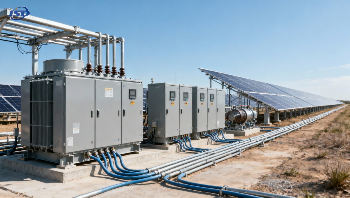
Where Cast Resin Dry-Type Transformers Fit
Dry-type technology is often considered for inverter stations where fire performance, reduced liquid-handling concerns, or indoor and enclosed installation arrangements influence the decision. It is not automatically preferable to an oil-filled unit in every solar farm; outdoor ambient conditions, enclosure ventilation, site maintenance practice, and project voltage level still determine the better fit. But where a cast resin design is appropriate, it can offer a robust insulation approach without liquid coolant.
For example, the 20kV Three-Phase Cast Resin Dry-Type Distribution Transformer is available for 20 kV input and 0.4 kV or 0.415 kV output applications, with capacities listed from 50 kVA to 5000 kVA. The SCB10-12 range includes common ratings such as 400 kVA, 630 kVA, 1000 kVA, 1250 kVA, and 2500 kVA. In a solar application, those figures should be viewed as a starting point for station sizing, not as proof that any selected rating will tolerate the actual harmonic profile.
Its ±2 × 2.5% high-voltage tapping range can be relevant where the collector voltage needs adjustment around expected system conditions. The stated IP23 protection class and F1 fire classification also need to be read in context: IP23 does not remove the need to assess rain exposure, dust ingress, condensation risk, or the design of the transformer room or inverter skid. A dry-type transformer’s ventilation path should remain clear throughout service life. Adding fine mesh, poorly placed acoustic lining, or an undersized air duct after installation can quietly raise operating temperature.
The specified capability for 120% rated load under forced-air cooling is useful only when the forced-air system, temperature monitoring, alarms, and maintenance access are included in the plant operating philosophy. It should not become a substitute for correcting an undersized transformer or unresolved harmonic loss issue. In practice, forced cooling is best treated as managed operating capacity with clear limits, not permanent invisible headroom.
Avoiding Resonance Around Cables and Reactive-Power Equipment
Many solar-farm harmonic problems emerge only after a change that seems unrelated to the transformer: another inverter block is energized, a capacitor bank is switched, a feeder is reconfigured, or a grid-side device changes control mode. Medium-voltage cables contribute capacitance, while transformers and the network provide inductive elements. Together, they can form resonant circuits. The more distributed the collector network becomes, the less reliable intuition alone becomes.
If a study identifies a resonance close to a material harmonic order, possible actions include changing capacitor-bank configuration, using detuned reactors where appropriate, adjusting cable or feeder arrangements, revisiting transformer impedance, or refining inverter filter and control settings. The right remedy depends on the system model. Simply adding a filter without checking its interaction with the network can move the problem rather than solve it.
Measurements during commissioning are valuable because models have limits. Voltage and current should be recorded at meaningful points, such as inverter outputs, the low- and medium-voltage transformer terminals, and the plant connection point where practical. Measurements should cover more than one sunny, steady period. Low-generation periods, transitions, reactive-power commands, and different numbers of inverters online can expose conditions that a single snapshot misses.
Protection, Monitoring, and the Signals That Deserve Attention
Transformer protection should not assume that all non-fundamental behavior is a fault. Relay settings, measurement transformers, and power-quality meters need adequate frequency response for the intended function. At the same time, differential protection, overcurrent protection, temperature alarms, and cooling alarms must remain selective and dependable under inverter-fed fault behavior, which can differ substantially from the contribution of rotating generation.
Temperature monitoring is particularly useful when it supports a trend rather than only a trip contact. A gradual increase in winding temperature at a similar load and ambient condition may indicate blocked airflow, loose connections, an altered harmonic condition, or cooling-system degradation. Audible noise changes, repeated inverter alarms, unusually warm cable terminations, and capacitor failures are also clues worth correlating with power-quality records.
Jinshida Electric Power Technology Co., Ltd. approaches power transmission and distribution equipment with an emphasis on application engineering as well as manufacturing quality. For solar projects, that distinction matters. A dependable transformer solution comes from disciplined design inputs, appropriate insulation and thermal margins, and a clear exchange of technical information among equipment suppliers—not from relying on a catalogue rating after the network design is already fixed.
A Practical Review Before Releasing the Transformer Order
Before the transformer specification is frozen, confirm that the inverter harmonic spectrum and operating modes have been issued in a usable form; that the study includes all planned cables and reactive-power devices; and that the transformer manufacturer has been told about harmonic duty, ambient conditions, installation arrangement, and expected loading profile. Check vector group, neutral treatment, impedance tolerance, tap requirements, cooling method, terminal layout, enclosure ventilation, and the interface to temperature-control signals.
For a medium voltage transformer for solar farms, the strongest decision is rarely the lowest-loss or lowest-cost option considered in isolation. It is the unit whose electrical characteristics have been coordinated with the inverter block and collector network, whose thermal capability is credible under the actual waveform, and whose installation can preserve that capability after years of dust, heat, cycling, and operational changes. That is the point at which harmonic management stops being a study deliverable and becomes reliable plant operation.

Get a Quote
Regardless of whether you require general advice or specific support, we are happy to help you.
Send Us Your Inquiry Today

Jinshida Electric remains committed to contributing to global energy development through professional manufacturing and superior service.