





Cast Resin Medium Voltage Transformers for Indoor Sites: Fire and Ventilation Criteria
Fire performance is a system property, not a transformer label
A cast resin medium voltage transformer is often selected for indoor substations because it eliminates free mineral oil from the transformer enclosure. That is an important fire-risk reduction measure, but it is not equivalent to proving that the installation is fire-safe. The transformer, room construction, cable entries, switchgear, ventilation path, protection settings, and emergency procedures all affect the final risk profile.
The most consequential mistake is treating a dry-type transformer’s fire classification as a substitute for a site fire assessment. A transformer tested to a defined fire-behaviour class may be appropriate for a higher fire-risk indoor location, but the classification does not determine whether the room needs fire-rated walls, smoke detection, cable fire stopping, mechanical extraction, or a dedicated fire compartment. Those requirements remain governed by the applicable installation rules, building regulations, insurer requirements, and the authority having jurisdiction.
For quality and safety control, the key question is narrower and more useful: does the supplied transformer have demonstrated insulation, fire, thermal, and environmental performance for the actual room and duty cycle—not merely for its nominal voltage and kVA rating?
Use IEC 60076-11 correctly
IEC 60076-11 is the principal international reference for dry-type power transformers. It covers technical requirements, testing, and classification concepts relevant to cast resin designs. A purchase specification should identify the applicable edition required by the project and state the agreed ratings, insulation levels, cooling method, environmental conditions, and any special fire-performance requirement.
Three IEC 60076-11 classification families are particularly relevant to an indoor cast resin transformer:
- Climatic class (C): addresses operation, transport, and storage at low ambient temperatures. The selected class must reflect the minimum temperature expected before energisation and during operation.
- Environmental class (E): addresses resistance to humidity, condensation, pollution, and related environmental effects. This is especially important in coastal facilities, tunnels, wastewater areas, process plants, and poorly conditioned electrical rooms.
- Fire-behaviour class (F): addresses the transformer’s behaviour under specified fire conditions. F1 is commonly specified where limited flammability and controlled fire behaviour are required.
These classes must not be specified by habit. An F1 requirement does not solve a condensation problem, and an environmental classification does not compensate for inadequate cooling. A specification such as “C2/E2/F1 or equivalent,” when genuinely justified by site conditions, is more meaningful than a generic statement that the transformer must be “fireproof” or “suitable for indoors.” Fireproof is not a technically useful procurement term for this purpose.
Where project documents cite IEC 61936-1 for power installations exceeding 1 kV AC, its relevance is broader than the transformer itself. It informs installation-level considerations such as access, earthing, segregation, clearances, and operational safety. Local electrical and building rules may impose additional requirements and take precedence where they are more stringent.
What an F1 declaration does—and does not—establish
Fire class F1 is valuable because it is based on a defined test framework rather than a marketing claim about resin properties. It is intended for transformers installed where fire hazard is a significant consideration. However, an F1 declaration should be reviewed as evidence tied to the transformer design being offered, not as a blanket statement applicable to every transformer that uses cast resin insulation.
The documentation review should establish whether the evidence applies to the proposed design: the same insulation system, winding construction, enclosure arrangement where relevant, voltage class, and manufacturer. A report or certificate with a broadly similar product description may not demonstrate conformity for a substantially different design, altered winding material, changed resin system, or revised cooling arrangement.
F1 also does not mean that the transformer cannot emit smoke, cannot be damaged by external fire, or can be installed without separation from combustible cable systems. In an indoor substation, the most significant combustible inventory may be cable insulation, cable trenches, terminations, panels, filters, packing materials, or stored maintenance supplies rather than the cast resin windings themselves.
A credible fire review therefore considers ignition sources and fire propagation routes. Cable openings through walls should be properly fire-stopped. Cable trenches and floor penetrations should not become routes for smoke migration. Where smoke control is required, ventilation dampers, louvres, and extraction arrangements need to be coordinated with the building fire strategy rather than designed only for heat removal.
Ventilation must be based on losses, not transformer capacity alone
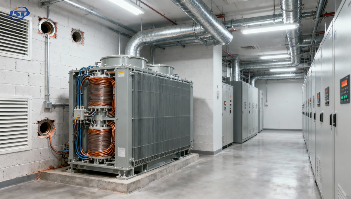
Indoor dry-type transformers release heat continuously through core losses and load losses. The thermal burden is not determined by rated kVA alone. Two transformers with the same capacity can have different loss values, and actual room temperature depends on loading profile, ambient air temperature, altitude, solar gain where applicable, adjacent equipment losses, and the resistance of the ventilation route.
A common design failure occurs when a transformer room is given nominal louvre area but no verified air path. Air enters and exits through openings that are too close together, recirculates at the ceiling, or is obstructed by acoustic louvres, mesh, filters, cable trays, or equipment placed near the transformer. The room may then meet a drawing requirement while still operating above the transformer’s permitted ambient conditions.
The ventilation calculation should use the manufacturer’s stated no-load and load losses at the relevant temperature reference, together with losses from MV switchgear, LV switchboards, auxiliary equipment, lighting, and any battery or UPS systems located in the same room. The design basis should state:
- maximum outdoor and indoor ambient temperature;
- permitted room temperature rise and transformer operating ambient;
- expected transformer load profile, including seasonal peaks and harmonic loading where relevant;
- natural or forced ventilation arrangement;
- louvre free area after allowing for blades, screens, insect mesh, filters, and pressure losses;
- air inlet and outlet locations, with a defined path across the transformer;
- fan duty, redundancy, power supply, alarm status, and failure response where mechanical ventilation is required.
Natural ventilation can be reliable when room geometry, heat load, and external conditions support sufficient stack effect. It becomes less predictable when intake and discharge openings are constrained by architecture, weather protection, acoustic treatment, security screens, or long duct runs. Forced ventilation should not be accepted merely because fans are installed. The required airflow must remain available under the pressure losses created by the final louvre, duct, and filter configuration.
Fan failure is a safety event when transformer loading cannot be reduced quickly enough to keep temperatures within design limits. Interlocks and alarms should reflect that reality. Depending on the operating philosophy, a high-room-temperature alarm may trigger remote notification, staged fan operation, load shedding, or transformer trip. The selected response must be coordinated with continuity requirements; an unnecessary trip can be disruptive, while an alarm without an actionable response may not control the overheating risk.
Temperature monitoring is not a substitute for adequate airflow
Cast resin transformer windings are commonly fitted with temperature sensors, often using PTC thermistors or resistance temperature detectors. These devices support alarm and trip functions, but their value depends on correct sensor placement, tested wiring, setpoint coordination, and a clear response procedure.
Temperature devices should be reviewed in relation to the insulation thermal class and the manufacturer’s stated limits. It is unsafe to assume that a generic alarm setting is suitable for every design. The sensor system should identify abnormal heating before insulation ageing accelerates or before a ventilation problem becomes severe. High temperature can result from sustained overload, blocked airflow, fan failure, harmonic current, loose connections, poor termination contact, unbalanced loading, or excessive ambient temperature.
Temperature protection should also be distinguished from room-temperature monitoring. Winding sensors indicate transformer thermal condition; room sensors may reveal ventilation failure earlier or identify hot-air recirculation. Both can be useful, but neither replaces inspection of the physical air route.
Where non-linear loads are substantial, the loading assessment needs more than a nameplate kVA comparison. Harmonic currents can increase winding and stray losses, while elevated ambient temperature reduces thermal margin. IEC 60076-12 provides guidance relevant to loading of dry-type power transformers, but the application should remain aligned with the manufacturer’s declared capability and the measured or calculated load spectrum.
Clearances are functional requirements, not empty floor space
Minimum clearances around a cast resin transformer serve several functions: they permit heat dissipation, avoid air short-circuiting, provide access for inspection, preserve electrical clearances, allow safe cable termination, and support emergency response. No universal distance should be copied into every project without reference to the manufacturer’s installation instructions and local installation requirements.
Clearance checks should include the transformer’s full installed configuration, not only the tank or coil footprint. Cable boxes, HV and LV termination zones, surge arresters, busduct interfaces, cooling ducts, enclosure doors, and removable panels can all require additional space. Access needed to inspect torque-marked terminations, clean surfaces, test sensors, or replace fans must remain available after cable trays and barriers are installed.
Electrical clearance assessment is separate from ventilation clearance. A room can have adequate physical space around the transformer but insufficient phase-to-earth or phase-to-phase clearance at exposed terminations for the applicable insulation level and installation arrangement. Conversely, a code-compliant electrical spacing arrangement can still restrict airflow if solid barriers are placed too close to ventilation surfaces.
Quality acceptance should focus on traceable evidence
The factory acceptance package should correspond to the exact unit or clearly identified production design. Routine test records are central. Depending on the applicable standard and contractual scope, the review may include winding resistance, voltage ratio and vector group verification, impedance voltage, no-load loss and current, load loss, applied-voltage testing, induced-voltage testing, and partial discharge measurement where specified by the standard and project requirement.
Partial discharge deserves careful interpretation. A low reported value is useful only when the test voltage, test method, measurement sensitivity, acceptance criterion, and applicable standard basis are known. A standalone statement that a transformer is “PD-free” is not a meaningful engineering conclusion. The report should identify the unit, date, test conditions, measured values, and pass/fail criterion.
Visual inspection at delivery should focus on issues that can compromise insulation integrity or cooling: cracks or chips in cast resin surfaces, signs of impact, damaged spacers, distorted support frames, loose hardware, contaminated windings, damaged terminal insulation, incomplete earth connections, and blocked ventilation passages. Surface marks are not automatically evidence of an insulation defect, but any crack extending toward a conductor, spacer, or high-field region warrants manufacturer assessment before energisation.
Moisture control remains relevant even though cast resin windings are more resistant to humidity than untreated insulation systems. Long storage in an unconditioned room, water ingress through roof leaks, condensation caused by intermittent heating, or construction dust deposits can undermine the intended environmental performance. Energisation should not proceed until the room is dry, clean, ventilated as designed, and free of temporary construction materials.
Do not transfer oil-transformer assumptions to cast resin installations
An indoor transformer decision may involve comparing dry-type and liquid-filled alternatives, but their fire and ventilation reviews are not interchangeable. For example, an 10kV/0.4kV Oil-Immersed Power Distribution Transformer using a liquid insulation system requires assessment of liquid containment, leakage control, fire point, fire separation, and the applicable local rules for liquid-filled equipment. The availability of less-flammable fluids, including natural esters, can change the risk assessment but does not eliminate the need for one.
Likewise, selecting a cast resin medium voltage transformer does not automatically permit installation in a smaller room or removal of fire barriers. The correct decision follows from the full installation design: fire classification, combustible exposure, room construction, ventilation capacity, protection philosophy, and maintainable clearance.
Conditions that should stop energisation
Before energisation, unresolved defects should be treated as operational barriers rather than minor commissioning observations. These include missing or unverified fire-class documentation where it is contractually required; ventilation fans that cannot demonstrate duty operation; blocked inlet or discharge paths; room temperatures above the design basis; unsealed cable penetrations in a required fire barrier; inaccessible or untested temperature alarm and trip circuits; damaged cast-resin insulation; unidentified loose connections; or missing protective earth bonds.
The most reliable indoor installation is not the one with the longest certificate list. It is the one where the transformer’s declared IEC performance, test evidence, room ventilation, fire compartment strategy, and commissioning records all describe the same installed condition. When those elements are checked together, the cast resin transformer can deliver the fire-risk and operational advantages for which it was selected without relying on assumptions that the equipment itself cannot guarantee.
Hot News
- 00
0000-00
How U.S. DOE efficiency rules affect distribution transformer manufacturers - 00
0000-00
How american type pad mounted transformer seismic qualification affects installation in California utility grids? - 00
0000-00
Do european compact substation transformer EMC compliance tests include conducted emissions up to 30MHz?
0000-00
Contact Us

Get a Quote
Regardless of whether you require general advice or specific support, we are happy to help you.
Send Us Your Inquiry Today

Jinshida Electric remains committed to contributing to global energy development through professional manufacturing and superior service.