





Medium Voltage Transformers for Industrial Plants: Matching Impedance to Motor Loads
Medium Voltage Transformers for Industrial Plants: Matching Impedance to Motor Loads
Selecting a medium voltage transformer for industrial plants requires more than matching primary voltage, secondary voltage, and kVA rating. In facilities with large pumps, compressors, crushers, conveyors, fans, or process drives, transformer impedance can determine whether motors accelerate cleanly or whether the plant experiences voltage dips, nuisance trips, weak starting torque, and difficult protection settings.
For technical evaluators, impedance is not a secondary nameplate detail. It is a system-design variable that sits between the utility source, transformer, MV or LV switchgear, cables, motor starters, variable-frequency drives, and the motors themselves. A transformer that appears adequate in steady-state load calculations may still be poorly matched to the plant’s operating profile if its impedance is too high for demanding starts or too low for the available interrupting and protection capabilities.
The practical objective is balance: enough impedance to limit fault current and support selective protection, but not so much that the transformer becomes a source of unacceptable voltage drop when major motors start or when several loads change simultaneously.
Why impedance matters beyond the nameplate
Transformer impedance, usually expressed as percent impedance or impedance voltage, represents the internal voltage drop associated with rated current. It is also the transformer’s principal contribution to short-circuit limitation. In simplified terms, a lower-impedance transformer supplies higher prospective fault current at its secondary terminals, while a higher-impedance transformer restricts it more strongly.
That relationship becomes especially important where motors are started across the line. An induction motor can draw several times its rated current during acceleration. The exact current and acceleration time depend on motor construction, load inertia, supply voltage, starter method, cable length, and driven equipment. If the transformer and upstream system have substantial impedance, the temporary current demand causes a voltage depression at the motor terminals. Since motor torque is strongly affected by voltage, a moderate-looking voltage drop can materially reduce available accelerating torque.
A motor that starts slowly remains at high current for longer. That can deepen the dip, heat conductors and equipment, disturb other loads, and lead to a failed start. In a process plant, the visible symptom may be a control-system reset or a contactor dropout rather than an obvious transformer problem.
Conversely, choosing very low impedance simply to strengthen motor starting can create another problem: the calculated short-circuit duty at switchgear, busbars, circuit breakers, CTs, and protective devices may rise beyond the design margin. The solution is rarely “choose the lowest impedance available.” It is to study the full electrical system and operating sequence.
Start with the motor-load picture, not the transformer catalogue
Before requesting transformer quotations, define how the plant actually behaves. A connected-load schedule is useful, but it is not enough. Technical review should identify the largest motor, the most difficult motor to start, normal operating combinations, standby philosophy, future expansion, and whether a loss of one transformer forces a remaining unit to carry essential loads.
The distinction between the largest motor and the hardest start matters. A high-power fan with a soft starter may be less demanding than a smaller loaded conveyor started direct-on-line. Pumps may impose a different duty depending on whether they start against a closed valve, while compressors and high-inertia machines can require a longer acceleration interval. Variable-frequency drives usually reduce starting current, but they introduce their own considerations: harmonic current, transformer heating, voltage distortion, grounding arrangement, and compatibility with the drive supplier’s recommendations.
The required inputs normally include:
- motor ratings, rated voltage, efficiency, power factor, and starting method;
- locked-rotor or starting-current information where available;
- driven-load torque and inertia characteristics for critical motors;
- motor starting sequence and the possibility of concurrent starts;
- transformer secondary cable lengths, bus arrangement, and feeder impedance;
- utility or generator source fault level and source impedance;
- switchgear short-circuit ratings and required protection coordination;
- expected additions, including future motor loads or process trains.
Without these inputs, a percent-impedance recommendation is usually only a preliminary assumption. A supplier can manufacture a transformer to an agreed impedance value, but only project studies can establish whether that value is appropriate for the actual network.
Voltage dip: the question that exposes weak selections
A useful early-stage check is to ask: what voltage will the critical motor see at its terminals during the worst credible start? The transformer’s impedance is part of that answer, along with the source, feeder, and motor circuit impedances. For initial screening, engineers often estimate transformer voltage drop by relating percent impedance to the temporary current expressed as a multiple of transformer rated current. That estimate is not a substitute for a load-flow or motor-starting study, but it quickly shows why transformer loading and motor starting cannot be reviewed separately.
A transformer operating close to its rating has less practical headroom for a large motor start than one carrying a lighter normal load. Parallel transformers add further complexity. Units with materially different impedance characteristics may not share load as intended, and their combined fault contribution must be evaluated. Similar voltage ratio, vector group, phase displacement, tap position, and impedance characteristics are normally important when transformers are expected to operate in parallel.
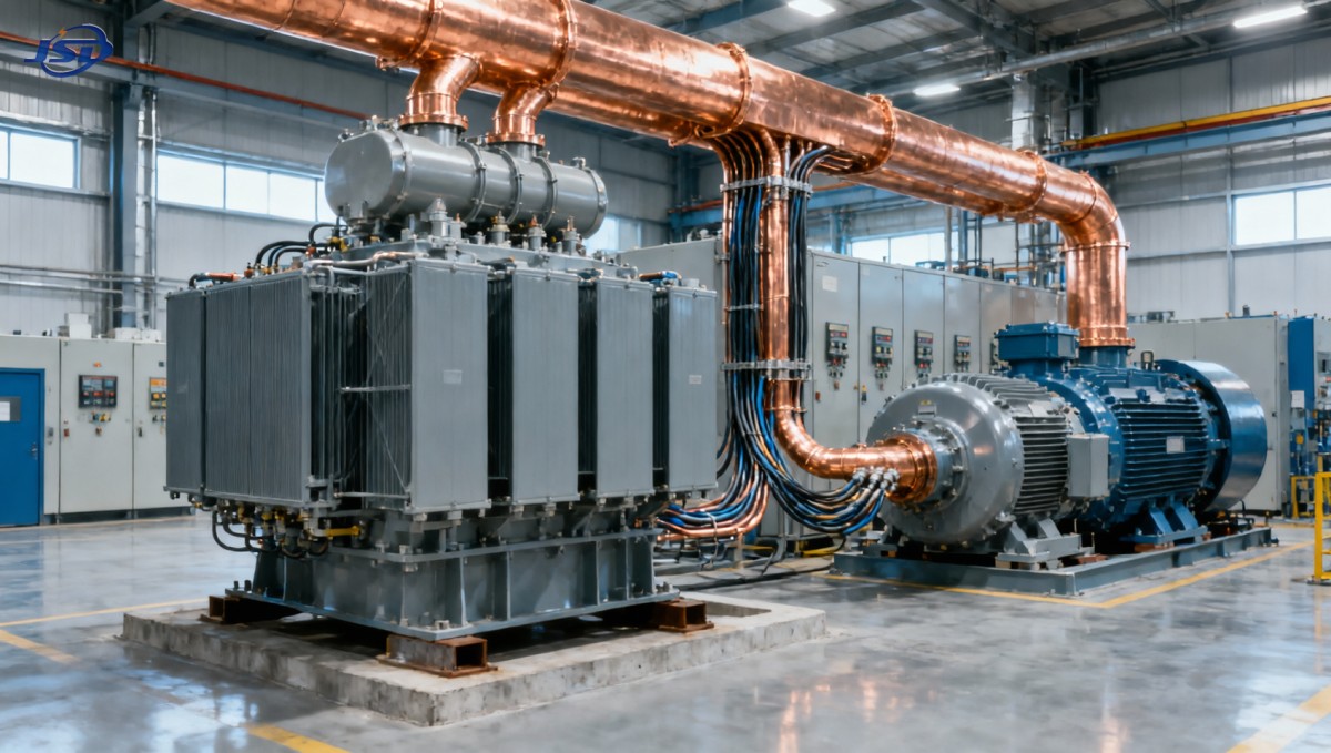
The acceptable dip is not universal. It depends on motor torque margin, contactors, control power, sensitive electronic loads, process continuity, and the site’s engineering criteria. A plant with conventional motor control centers may tolerate a condition that would be unacceptable in an automated process line with sensitive instrumentation. The evaluation should therefore consider the voltage at several locations: transformer secondary bus, switchboard bus, and motor terminals.
Fault-current control and protection coordination pull in the other direction
Lower transformer impedance generally improves stiffness at the secondary bus during a motor start, but it increases the transformer’s short-circuit contribution. This can affect the required interrupting capacity of downstream breakers, the short-time withstand rating of switchgear, busbar bracing, arc-flash assessment, and relay settings. In an existing plant, replacing an older transformer with a lower-impedance unit can alter the fault-duty calculation even if the kVA rating and voltage ratio remain unchanged.
Higher impedance reduces available fault current, which can help keep equipment duty within limits. Yet excessive impedance may make overcurrent protection less sensitive to faults at remote feeder ends, depending on the grounding system and protective scheme. Ground-fault behavior must be reviewed separately from three-phase fault current; transformer winding connection and neutral grounding method are central to that assessment.
This is why impedance should never be selected from a single rule of thumb. The protection engineer needs the final transformer impedance, tap range, vector group, earthing arrangement, and source data before settings are finalized. If any of those values change during procurement, the coordination study should be revisited rather than treated as a paperwork formality.
Choosing an impedance range: a disciplined decision process
A sound specification does not begin with a preferred percentage. It begins with constraints. Determine the maximum fault duty that installed or planned switchgear can safely accommodate. Identify the minimum voltage needed by the critical motor during acceleration. Then model credible operating cases: normal source, alternate source, parallel transformer operation if applicable, emergency generation, and the arrangement after a feeder or transformer outage.
The preferred impedance is the value, or narrow range of values, that satisfies both sides of the problem. It should be documented together with the assumptions used to reach it. That documentation is valuable later when operations teams question a start-up issue or when expansion changes the electrical balance.
Do not isolate transformer selection from plant resilience
Industrial electrical design is increasingly shaped by resilience requirements. Some sites need essential control loads, communications, emergency lighting, or selected low-voltage auxiliaries to remain available during source transitions. These requirements do not change the impedance calculation for a medium-voltage transformer, but they do influence the overall one-line diagram, protection philosophy, and restoration sequence.
For smaller backup or local energy-storage duties, a compact solution such as the 51.2V Wall-mounted LiFePO4 Energy Storage Battery may be considered as part of a separate low-voltage storage and inverter arrangement. Its 51.2 V, 100 Ah configuration provides 5.12 kWh nominal energy, with CAN and RS485 communications and an integrated battery management system. Those features can be relevant to residential, light-commercial, or auxiliary backup designs, but they should not be presented as a substitute for correctly sizing the industrial transformer or for verifying motor-starting performance. The two decisions operate at different voltage levels and serve different functions.
Specification details that deserve attention
When procuring a medium voltage transformer for industrial plants, specify the guaranteed impedance and the permitted manufacturing tolerance in line with the applicable project standard. Also define the impedance reference basis clearly: rated kVA, principal tap, frequency, and temperature conditions where required by the governing specification. A number written without its basis can lead to avoidable ambiguity.
Other details interact with impedance in practice. Tap changer type and range affect voltage-management options but do not solve an inherently weak motor-starting design. Vector group affects grounding and protection. Cooling class affects available loading capability. Winding material, insulation system, enclosure requirements, altitude, ambient temperature, seismic requirements, and installation environment influence construction and thermal design. If nonlinear loads are substantial, harmonic assessment should be completed early enough to determine whether derating or a purpose-designed transformer is appropriate.
Factory routine tests and any agreed type, special, or witnessed tests should be identified before manufacture. Site acceptance should verify not only ratio and insulation-related checks required by the project, but also phasing, grounding continuity, protection interfaces, and the intended tap position. Commissioning is the time to compare study assumptions with the equipment actually delivered.
A better technical handover to the transformer manufacturer
The best supplier engagement begins with a usable data package rather than a bare request for “an industrial transformer.” At minimum, provide the single-line diagram, voltage levels, rated power, required impedance range, vector group, insulation level, tapping requirements, installation conditions, loss-evaluation requirements where applicable, and relevant testing or documentation standards. Share the short-circuit and motor-starting study assumptions when they are available.
Jinshida Electric Power Technology Co., Ltd. approaches power transmission and distribution projects through engineering, manufacturing, and application support rather than treating the transformer as an isolated commodity. For industrial manufacturing, grid, new-energy, and infrastructure applications, that means confirming electrical parameters against the wider distribution system, then applying controlled manufacturing processes and quality management to support stable service in the field.
A technically credible proposal should state the offered impedance explicitly and identify any departures from the requested requirements. It should also make clear which system studies remain the owner’s or engineering consultant’s responsibility. This transparency is preferable to an apparently attractive quotation that leaves key electrical interfaces undefined.
The final decision should survive changing operating conditions
The right medium voltage transformer for industrial plants is not necessarily the largest unit, the lowest-impedance unit, or the lowest-loss unit considered in isolation. It is the unit whose impedance, thermal capability, voltage regulation, fault contribution, winding connection, and protection interfaces fit the operating plant.
Before releasing an order, test the proposed design against the hardest motor start, the highest credible source fault level, and the most constrained operating configuration. Confirm how future expansion will affect both voltage dip and short-circuit duty. If the answer changes when a second transformer is paralleled, a generator is connected, or a large motor is added, those conditions belong in the design review now—not after equipment arrives on site.

Get a Quote
Regardless of whether you require general advice or specific support, we are happy to help you.
Send Us Your Inquiry Today

Jinshida Electric remains committed to contributing to global energy development through professional manufacturing and superior service.