





Managing Harmonics and Heat in Distribution Transformers for Data Centers
Managing Harmonics and Heat in Distribution Transformers for Data Centers
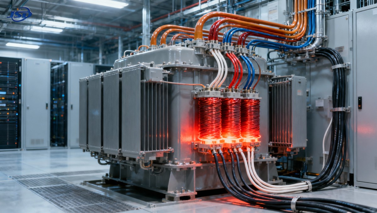
Data centers place exceptional demands on power infrastructure. Their electrical load is dense, highly dynamic, and increasingly shaped by nonlinear equipment: UPS systems, server power supplies, variable-speed cooling drives, battery chargers, and power electronic interfaces. These loads can introduce harmonic currents that do not simply disappear at the rack level. They travel upstream, adding losses and heat in cables, switchgear, and distribution transformers for data centers.
For maintenance teams, the concern is not merely a high temperature alarm. Harmonic-related heating can accelerate insulation aging, increase neutral loading, reduce available capacity, and make a transformer appear overloaded even when the fundamental kVA demand seems reasonable. In a facility where uptime is the operating priority, transformer condition must be evaluated in the context of waveform quality, load profile, cooling conditions, and the reliability of the monitoring data itself.
Why Data Center Loads Change the Thermal Picture
A conventional transformer loading assessment often begins with rated capacity and average current. That remains necessary, but it is not sufficient for a modern data center. Most IT loads draw current in pulses rather than as a smooth sinusoidal waveform. The resulting harmonic components increase RMS current and create additional losses in transformer windings, core steel, structural parts, and connections. Those losses are converted directly into heat.
Triplen harmonics, particularly the third harmonic and its multiples, deserve close attention in low-voltage systems. In a three-phase, four-wire arrangement, these components can add in the neutral rather than cancel. A neutral conductor, terminal, or busbar that appears conservatively sized for balanced fundamental current may therefore run hotter than expected. Harmonics can also cause circulating currents in delta windings and contribute to eddy-current loss in conductors.
The situation becomes more complicated when data halls expand in phases. A transformer that operated comfortably during initial commissioning may later support more racks, a different UPS topology, or upgraded cooling equipment. The total kW increase matters, but so does the changed harmonic signature. Maintenance teams should treat every major load change as a reason to review power quality and thermal margins rather than relying only on historical loading figures.
Heat Is an Operating Condition, Not Just a Nameplate Question
Transformer temperature reflects several conditions at once: ambient temperature, load current, harmonic content, cooling medium condition, airflow or radiator performance, terminal resistance, and the transformer’s recent load history. A short high-load event may not immediately produce a critical oil or winding temperature, while repeated thermal cycling can still stress insulation over time. This is why a single manual temperature reading gives only part of the story.
For oil-immersed units, maintenance personnel should distinguish between top-oil temperature and the hottest winding condition. Top-oil temperature is valuable, but winding hot-spot temperature is more directly related to insulation stress. Where direct winding measurement is not available, it may be estimated through an approved thermal model using load and oil-temperature inputs. The calculation method, sensor placement, and alarm thresholds should be aligned with the transformer design documentation and the facility’s operating procedures.
A persistent temperature rise should not be dismissed as “normal data center heat.” First rule out practical causes: obstructed radiators, failed fans where forced cooling is used, dirty surfaces, inadequate enclosure ventilation, degraded oil condition, loose bolted joints, or a poorly balanced phase load. Infrared inspection is useful for identifying abnormal connections and uneven thermal patterns, but it should be performed under meaningful load and interpreted alongside electrical measurements.
Measure Harmonics Where Decisions Can Be Made
A portable power quality analyzer can reveal much more than a total harmonic distortion figure. For transformer maintenance, useful measurements include voltage and current waveform capture, harmonic spectrum by order, true RMS current, neutral current, phase imbalance, demand trend, power factor, and crest factor. Measurements should normally be taken at the transformer secondary and, where practical, at significant downstream distribution points. This helps determine whether the issue is created by the combined facility load or concentrated in one UPS, panel, or cooling branch.
Do not judge a transformer only by voltage distortion. A relatively clean voltage waveform can coexist with substantial harmonic current and extra winding loss. Current harmonics are often the more immediate thermal concern for transformers. Likewise, a low harmonic reading taken during a quiet operating period may be misleading if the data hall reaches its peak during batch processing, high cooling demand, or transfer events involving UPS equipment.
Trending is more useful than isolated testing. Establish a baseline after commissioning or after a known-good maintenance event, then compare subsequent readings under similar loading conditions. A gradual rise in neutral current, temperature differential between phases, or harmonic current can expose a developing issue before it becomes an outage risk. Event logs should also be checked after generator tests, UPS bypass operations, capacitor switching, or major IT load additions.
What to investigate when temperatures rise
- Compare phase currents and neutral current with previous baselines, not only with nominal rating.
- Review harmonic current by order and identify whether triplen components are prominent.
- Inspect secondary terminals, cable lugs, bus duct interfaces, and grounding connections for local hot spots.
- Confirm that cooling equipment, enclosure ventilation, and radiator clearances match the installed configuration.
- Review changes to UPS settings, cooling controls, server density, and load-transfer sequences.
Selecting and Applying the Right Transformer Margin
The correct response to harmonics is not always to oversize the transformer. Extra capacity may lower normal load temperature, but it does not automatically address harmonic eddy losses, neutral loading, or a poor system configuration. The transformer design, winding arrangement, impedance, conductor sizing, cooling class, and expected harmonic spectrum all deserve review. In some projects, a transformer specifically designed for nonlinear loading may be appropriate; in others, harmonic mitigation upstream or downstream is the more effective intervention.
Transformer sizing should be based on the expected electrical environment rather than connected load alone. Maintenance staff can contribute valuable operating evidence to this decision: actual peak demand, growth pattern, load diversity, measured harmonic spectrum, temperature history, and the duration of contingency loading. Engineering teams should then verify the result against applicable IEC, ANSI/IEEE, utility, and local installation requirements. The relevant standard and design approach can vary by project location and facility architecture.
For a 20 kV distribution arrangement stepping down to 0.4/0.415 kV, the 20kV/0.4kV Oil-Immersed Power Distribution Transformer is one possible configuration for data center applications where the site layout, fire-safety provisions, and local requirements support oil-immersed equipment. Its stated capacity range of 50 kVA to 5000 kVA and 50/60 Hz compatibility give project teams room to match the unit to the actual distribution scheme. However, the final selection still needs to account for nonlinear load behavior, fault level, protection coordination, installation environment, and required redundancy.
Where FR3 vegetable oil is selected, it should be considered as part of the wider risk and maintenance strategy, not as a substitute for thermal management. Fluid choice, transformer placement, containment arrangements, fire protection, and local code requirements must be reviewed together. Similarly, an IP65 enclosure rating may help protect equipment against dust and moisture in suitable installations, but it does not remove the need to manage heat dissipation around the transformer.
Practical Harmonic Mitigation Without Creating New Problems
Harmonic filters can be effective, but they should not be installed simply because a distortion value appears high. Passive filters, active harmonic filters, phase-shifting arrangements, and higher-pulse rectifier configurations each have different effects on the network. A poorly coordinated passive filter may interact with system impedance or capacitors. Active filtering can adapt to changing load conditions, yet it requires proper sizing, monitoring, and maintenance. The best option depends on the measured spectrum and the electrical architecture.
Load segregation can sometimes produce a cleaner outcome than adding a large mitigation device. Separating high-distortion UPS loads from other sensitive or less tolerant loads may reduce stress on a common transformer. Balancing single-phase loads across phases remains basic but important housekeeping. In rapidly evolving data halls, it is easy for incremental rack additions to create a pattern that was not present in the original design.
Avoid treating power-factor correction and harmonic reduction as the same task. Capacitor banks can improve displacement power factor, but in a harmonic-rich network they must be evaluated carefully. Their interaction with harmonic frequencies may worsen conditions if the system is not properly engineered. Before changing capacitor settings or adding correction equipment, review the harmonic study, transformer impedance, and the operating state of major power electronic loads.
A Maintenance Routine Built Around Early Evidence
The most dependable maintenance routines combine condition monitoring with scheduled physical checks. Review temperature and load trends routinely, but also inspect external condition, corrosion, leaks, seals, terminations, grounding, cooling surfaces, and associated protection devices. For oil-filled transformers, oil testing and dissolved gas analysis may be appropriate depending on unit size, criticality, service history, and maintenance plan. Results should be trended and interpreted by qualified personnel rather than used as stand-alone pass or fail indicators.
Alarm thresholds need practical escalation rules. An alarm that generates repeated notifications without a clear response path will eventually be ignored. Define what requires observation, what requires a power quality survey, what requires reduced loading, and what requires immediate engineering review. Include temporary operating modes, such as N+1 equipment out of service or generator-supported operation, because these are often the periods when transformers experience their highest sustained thermal stress.
Jinshida Electric Power Technology Co., Ltd. approaches distribution equipment through R&D, manufacturing discipline, and application-focused technical support. For critical facilities, that approach matters because transformer reliability is not created by one nameplate value. It comes from matching the equipment to the voltage system and load behavior, maintaining manufacturing and quality controls, and giving site teams the information needed to inspect and operate the equipment consistently.
When reviewing distribution transformers for data centers, start with the actual waveform and thermal history, then work outward to configuration and equipment capability. Confirm the peak and contingency load profile, harmonic spectrum, neutral current, cooling conditions, transformer design assumptions, and required certification or installation standards. That sequence is more likely to uncover the real cause of heating than a simple decision to add capacity after the fact.

Get a Quote
Regardless of whether you require general advice or specific support, we are happy to help you.
Send Us Your Inquiry Today

Jinshida Electric remains committed to contributing to global energy development through professional manufacturing and superior service.