





Load Tap Changer Selection for Substation Power Transformer Retrofits
A retrofit can look straightforward on a single-line diagram: replace an aging transformer, retain the existing bay, and improve voltage control. In practice, the load tap changer often becomes the decision that determines whether the outage window, protection settings, civil works, and operating plan remain manageable. The right choice is not simply the LTC with the widest voltage range or the highest number of tap positions. It is the arrangement that can regulate the required bus voltage without overstressing the transformer, disrupting protection coordination, or creating maintenance obligations the site cannot support.
For a substation power transformer with load tap changer, the first selection decision is usually this: confirm whether automatic on-load regulation is genuinely required at the transformer and, if it is, define the voltage-control duty before choosing the tap changer design. A retrofit should begin with measured operating conditions, not with the nameplate of the transformer being removed. Historical voltage records, loading patterns, feeder behavior, available fault levels, and the existing control philosophy often reveal constraints that are not visible in the original equipment specification.
Start with the voltage problem the retrofit must solve
An LTC is intended to change the transformer ratio while energized and carrying load. It is appropriate when voltage variation is frequent enough that an off-circuit tap setting would leave the secondary bus outside its acceptable operating band during normal operation. This commonly occurs where supply voltage varies, long outgoing feeders create changing voltage drop, reactive power flows shift through the day, or generation connected downstream changes net load direction.
The critical question is not “Does the existing transformer have an LTC?” but “What regulation function is needed after the retrofit?” An old unit may have been fitted with an LTC because of historical network conditions that no longer apply. Conversely, a fixed-ratio replacement may appear economical until seasonal loading or distributed generation causes persistent voltage complaints and repeated manual interventions.
Before issuing a request for quotation, separate the voltage issue into three parts:
- Source-side variation: Determine the normal and extreme voltage range presented to the transformer high-voltage terminals.
- Transformer and bus requirement: Define the desired controlled voltage, allowable deadband, and the range that connected equipment can tolerate.
- Downstream network behavior: Identify feeder voltage drop, capacitor switching, large motor starts, renewable generation export, and parallel transformer operation that can affect the control point.
These inputs establish the required regulation range and control accuracy. They also prevent a common error: selecting a broad tap range to solve a downstream feeder issue that is better addressed through feeder regulation, conductor upgrades, reactive compensation, or a revised control scheme.
Decide whether on-load regulation is the right tool
There are three broad retrofit paths. The best path depends on operating duty rather than on what is easiest to describe in a procurement document.
Retaining an LTC is usually justified where the bus is a voltage-control point for multiple feeders, where voltage compliance is sensitive to changing load, or where a transformer operates in parallel and must follow a coordinated control strategy. By contrast, a compact distribution installation supplying relatively stable local loads may only need an off-circuit setting selected during commissioning. The selection should follow the operating evidence, not an assumption that “more control” is automatically better.
At the lower-voltage end of a distribution system, an oil-immersed unit may be a better fit when the duty does not require on-load ratio changes. For example, a 20kV/0.4kV Oil-Immersed Power Distribution Transformer is designed for 20 kV to 0.4/0.415 kV distribution applications and is available across a 50 kVA to 5000 kVA range. That type of equipment should be evaluated as a distribution-transformer solution, rather than assumed to be a substitute for a substation LTC retrofit where continuous bus-voltage control is essential.
Tap range and step size must work together
Once on-load regulation is confirmed, specify the total range, number of positions, and nominal step voltage as one system. A wide range with large steps may create noticeable bus-voltage movement at every operation. Very small steps can offer finer control but may increase the number of operations if controller settings are poorly coordinated. Neither feature is inherently superior.
Use recorded voltage and load data to model the expected operating envelope. The preferred neutral position should leave practical regulating room in both directions. If normal operation sits close to one end of the tap range, the transformer ratio or nominal voltage basis may be wrong for the actual network. Starting near the center of the range generally improves resilience to source changes and future load development, but it must be checked against the real voltage profile rather than treated as a universal rule.
The controlled-voltage target also needs a tolerance. A controller that attempts to hold an unrealistically narrow band can cause excessive tap operations, especially when measurement noise, capacitor bank switching, or short-duration load changes are present. A usable design defines:
- target voltage at the sensing point;
- deadband around that target;
- intentional time delay before a tap command;
- line-drop compensation settings, where applicable;
- upper and lower tap limits; and
- an alarm and response plan for excessive operations.
These control parameters are not minor commissioning details. They directly influence contact wear, motor-drive duty, voltage stability, and how long the LTC can remain in service between maintenance interventions.
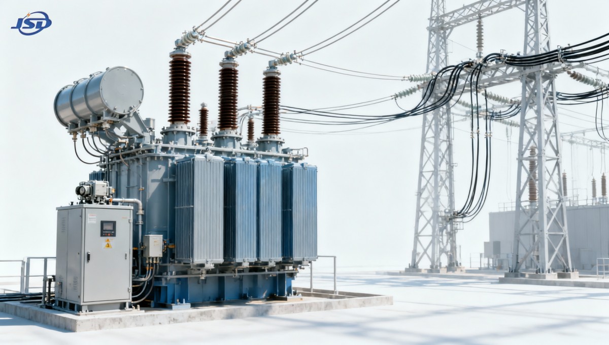
Check the transformer design, not only the tap changer catalog
An LTC retrofit is a transformer-system selection. The regulating winding, main winding, insulation arrangement, bushings, leads, diverter switch compartment, oil handling arrangement, and cooling capability must all suit the required duty. Simply comparing an LTC’s rated current with transformer load current is incomplete.
Start with the transformer’s rated MVA, voltage ratio, vector group, impedance, insulation level, cooling stages, and expected overload profile. The rated through-current at the LTC location must be verified for every relevant operating condition, including emergency loading and parallel operation. Where power flow can reverse because of embedded generation, confirm that the selected control and tap changer arrangement is suitable for bidirectional current and the intended control logic.
Winding location matters as well. Depending on the transformer design, the regulating winding may be associated with the high-voltage or low-voltage side. The choice affects insulation coordination, current duty, physical configuration, and the way tap changes influence the system. The correct arrangement should be established through transformer design review, not selected by a generic preference.
Thermal performance deserves particular attention in an upgrade. Increased utilization of an existing substation often drives the retrofit, but the load profile may include peaks that challenge the cooling system and insulation aging margin. A stated short-term overload capability is not a blanket allowance for repeated overload operation; it depends on temperature monitoring, ambient conditions, cooling availability, and the transformer’s thermal design. The LTC’s switching duty under these conditions must be considered alongside winding hot-spot and oil-temperature limits.
Fit the equipment into the existing substation
Physical constraints can rule out otherwise suitable options. Retrofit surveys should capture more than transformer footprint and total height. Review lifting routes, rail spacing, foundations, oil containment, fire separation, cable sealing, bushing clearances, marshalling cabinet access, control-cable routes, and the ability to remove or service the LTC diverter switch. A design that fits on a general arrangement drawing may still be difficult to maintain if the motor-drive mechanism or inspection cover cannot be safely accessed.
Oil containment and compartment design require special review when an LTC is added. Many on-load tap changers use a separate oil volume from the main transformer tank because switching contacts generate gases and oil degradation products over time. The retrofit scope must therefore account for separate oil sampling, filtration practices, pressure-relief provisions, monitoring connections, and any changes to containment capacity. Do not assume the existing oil pit, piping arrangement, or fire-protection layout remains adequate after the equipment configuration changes.
Environmental conditions should also be written into the specification: altitude, ambient temperature range, humidity, contamination, seismic requirement where applicable, and indoor or outdoor installation. These factors influence cooling margins, enclosure selection, bushing creepage requirements, cabinet protection, and corrosion protection. They are particularly important when a replacement unit is expected to remain in a constrained legacy bay for decades.
Protection and control integration often decides retrofit risk
A transformer replacement may retain much of the existing protection panel, but LTC operation introduces signals and interlocks that must be checked deliberately. At minimum, the engineering team should map the motor-drive supply, raise/lower commands, local/remote selection, tap position indication, limit switches, alarms, blocking contacts, and supervisory interface. The actual tap position must be reliably available to the control system when it affects parallel operation, voltage control, or asset monitoring.
Protection settings should be reviewed after any change in transformer impedance, vector group, rated voltage, CT ratio, or tap range. Differential protection compensation, overcurrent coordination, restricted earth fault arrangements, neutral grounding interfaces, and voltage-dependent control functions may all require recalculation or functional testing. A retrofit is not complete because the new transformer energizes successfully; the protection must continue to discriminate correctly across the full intended tap range.
Parallel transformers need a specific control plan
Parallel operation is one of the areas where a poorly specified LTC can create circulating current and unnecessary operations. Transformers sharing a bus should have compatible voltage ratios, vector groups, impedances, tap ranges, and tap step characteristics. Their controllers also need a defined operating mode: master-follower, circulating-current compensation, negative-reactance compensation, or another scheme justified by the network design.
Do not rely on independent automatic controllers to “settle themselves” when units are paralleled. Different voltage sensing points, unequal time delays, mismatched deadbands, or incorrect tap-position feedback can cause tap hunting. The procurement specification should require an agreed control philosophy and a commissioning test sequence for both single-transformer and parallel-transformer states.
Match maintenance strategy to expected operating duty
An LTC is a serviceable mechanical switching device, so lifecycle planning should begin before purchase. Review expected annual tap operations, permissible switching duty, inspection intervals, contact wear indicators, motor-drive maintenance requirements, oil test access, and availability of replacement parts. The best technical selection can still become an operational burden if the site has no planned outage access or no practical method for condition assessment.
Condition monitoring can be valuable where tap activity is high or outages are difficult to arrange. Depending on the chosen design and project requirements, this may include tap position monitoring, operation counters, motor-drive current or torque trend monitoring, oil condition monitoring, moisture indication, temperature data, and alarm integration. Monitoring should be selected to support a defined maintenance decision, not merely because a signal is available.
For installations where reduced routine intervention is a primary goal, it is useful to distinguish between the transformer enclosure and the LTC service requirement. An IP65-protected distribution transformer configuration may help address dust and moisture exposure in suitable applications, but an on-load tap changer still needs maintenance planning based on its switching duty and manufacturer instructions. Protection rating does not eliminate internal mechanical maintenance.
Build procurement requirements around acceptance, not assumptions
A vague requirement for an “LTC-equipped transformer” leaves too many critical items open to interpretation. The technical schedule should state the voltage regulation objective, required range and step arrangement, rated current and duty, control mode, sensing location, communication needs, parallel-operating requirement, alarm list, environmental conditions, and site interface constraints. It should also identify the documents needed for review: dimensional drawings, terminal diagrams, control schematics, losses and impedance data, tap position tables, protection interface information, routine test records, and commissioning guidance.
Factory and site acceptance planning should cover the complete control chain. Confirm motor-drive operation, raise/lower logic, position indication, limit functions, alarm contacts, remote commands, voltage-controller behavior, and any parallel-control blocking logic. At site level, verify the actual sensing polarity and voltage reference before enabling automatic control. Incorrect polarity or an incorrect compensation setting can drive the LTC in the wrong direction even when every component has passed individual tests.
Finally, preserve the operating data that informs future decisions. Record the initial tap position, controller settings, voltage readings under representative load, transformer temperatures, and alarm status at handover. After the first period of operation, compare tap-operation counts and bus-voltage performance with the design assumptions. A rising operation count, repeated limit position, or persistent voltage deviation is an early sign that the control settings or wider network arrangement needs review rather than a problem to be ignored until the next planned outage.

Get a Quote
Regardless of whether you require general advice or specific support, we are happy to help you.
Send Us Your Inquiry Today

Jinshida Electric remains committed to contributing to global energy development through professional manufacturing and superior service.