





Diagnosing Contact Wear in Substation Power Transformer Load Tap Changers
Diagnosing Contact Wear in Substation Power Transformer Load Tap Changers
Contact wear in a substation power transformer with load tap changer is rarely an isolated mechanical issue. It usually appears as a combination of changing electrical signatures, unstable voltage control, oil contamination, abnormal operating noise, or increasingly frequent tap-changer alarms. Left alone, worn contacts can raise transition resistance, create excessive local heating, damage the diverter switch, and eventually turn a manageable maintenance finding into an unplanned outage.
The practical difficulty is that an on-load tap changer (OLTC) is designed to interrupt and transfer current repeatedly without taking the transformer out of service. Some contact marking, limited erosion, and oil darkening are therefore expected over its service life. The maintenance question is not whether a contact looks used. It is whether the observed wear is still consistent with the changer’s duty, contact design, and maintenance limits—or whether it indicates deteriorating switching performance.
A useful diagnosis starts with operating history rather than opening the OLTC compartment immediately. A visual inspection can reveal serious damage, but the trends that explain why it happened are often found in the tap operation counter, voltage records, relay events, motor-drive behavior, and oil test results.
Why OLTC Contacts Wear Differently from Main Transformer Contacts
In a conventional OLTC, current transfer is shared by several elements: selector contacts choose the required tap position, transition contacts bridge the changeover interval, and the diverter switch performs the rapid current transfer. The exact arrangement differs by manufacturer and OLTC type, but the diagnostic principle remains the same: contacts exposed to arcing and transition duty generally age faster than contacts used mainly for position selection.
Transition contacts and diverter contacts are especially vulnerable because each operation can generate an arc during the interruption or transfer sequence. Over time, this may produce pitting, cratering, material transfer, rough surfaces, or reduced contact pressure. Carbonized particles and metal debris may enter the OLTC oil. If the contact face becomes uneven or spring force declines, resistance can rise even when the changer still completes a tap operation.
Not every defect is caused by normal electrical duty. Misalignment, slow drive movement, incorrect timing, contaminated oil, a weak mechanism spring, or an improperly adjusted transition circuit can accelerate wear. That distinction matters. Replacing contacts without finding the initiating cause may simply reset the clock for the next failure.
Operational Clues That Deserve Investigation
The first clue is often a change in voltage-regulation behavior. A transformer may appear to hunt between tap positions, remain longer than expected at a tap limit, or show voltage steps that do not correspond cleanly with the commanded position. These symptoms do not prove contact wear; problems in the automatic voltage regulator, potential transformer circuit, control wiring, or parallel-control scheme can produce similar behavior. Still, they should trigger a review of the complete tap-changing sequence.
A rising operation count is another warning sign, particularly where load patterns have changed. Renewable generation, industrial process loads, and frequent feeder voltage variation can increase the number of daily tap changes substantially. A substation power transformer with load tap changer that was originally operated under steady demand may face far more switching duty after a network reconfiguration or the addition of distributed energy resources. Maintenance intervals based only on calendar time can then become misleading.
Maintenance teams should pay close attention to:
- Repeated motor-drive failures, incomplete operations, or unusually long operating times.
- Changes in OLTC compartment oil color, odor, sediment, or dielectric condition.
- Gas generation trends that point toward arcing in the tap-changer oil space, where separate oil is used.
- Unexpected temperature differences at external OLTC terminals or cable connections.
- Irregular acoustic sound during a tap change, including delayed or double mechanical impacts.
- Tap-position indications that disagree with the mechanical position or control-system record.
One isolated event may have an innocent explanation. A pattern across several records is more valuable. For example, slow motor-drive operation combined with worsening transition resistance and darkened OLTC oil points in a much clearer direction than any one observation by itself.
Build the Diagnosis Before Opening the Compartment
Before scheduling an internal inspection, collect the evidence that can be obtained safely with the transformer in its normal operating state. Start with the nameplate data and the OLTC manufacturer’s service documentation. Contact limits, allowable erosion, inspection intervals, lubrication points, and test methods are design-specific. A maintenance team should not rely on generic visual criteria when the equipment manual provides defined limits.
Review the tap counter against the last overhaul or contact replacement. Then compare recent operation frequency with historical patterns. It is also worth checking whether automatic voltage control settings have become overly sensitive. A narrow deadband, inappropriate time delay, or conflicting parallel-transformer control can force unnecessary tap changes. In that situation, the contacts are showing the consequence of a control issue rather than an inherently defective OLTC.
Electrical testing should be selected according to the outage scope and the available equipment. Dynamic resistance measurement is particularly useful because it records resistance behavior while the OLTC moves through a tap transition. A smooth and repeatable trace across positions is generally more reassuring than a trace with sharp discontinuities, erratic peaks, or inconsistent patterns. The result should be compared phase-to-phase and, where reliable historical records exist, against the same transformer’s previous measurements.
Static winding resistance measurements can also reveal abnormal resistance at selected positions, although they may not expose every dynamic switching defect. Transformer turns-ratio testing confirms whether the expected ratio changes occur at the selected positions. Neither test replaces an internal inspection where severe contact wear is suspected, but together they help decide whether a planned maintenance window should become a priority.
What to Look for During Internal Inspection
Internal work must follow the transformer and OLTC manufacturer’s isolation, discharge, oil-handling, and access procedures. An OLTC mechanism may retain stored mechanical energy, and entering a compartment without proper preparation creates risks beyond the electrical system itself. Cleanliness is equally important: introducing moisture, fibers, or loose hardware into the compartment can create a new failure mechanism during what was intended as corrective work.
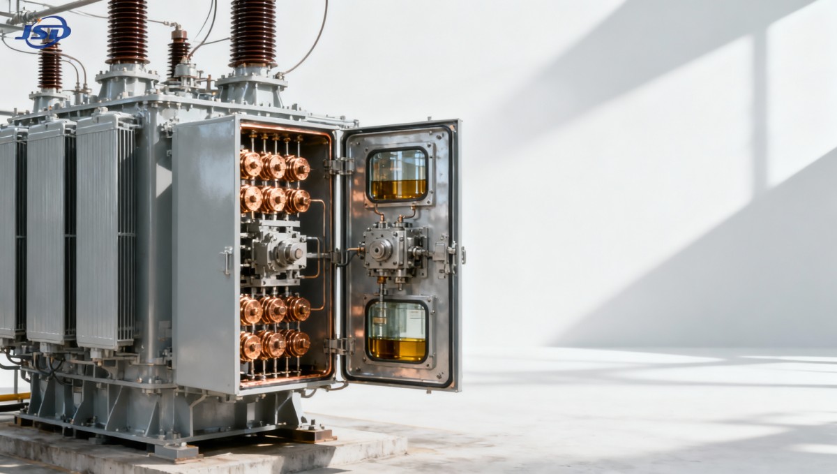
Examine contacts under good lighting and document the condition before cleaning or replacement. Light, even polishing may be normal. Deep pits, burned edges, contact material loss, severe discoloration, melted deposits, cracking, or uneven wear demand closer attention. Compare corresponding contacts between phases where the design permits. A single phase with substantially greater erosion can indicate unequal current transfer, a timing problem, contact-pressure loss, or a mechanism issue local to that phase.
Do not judge contact condition by appearance alone. Check alignment, wiping action, contact pressure where specified, fastener security, springs, linkages, and the diverter mechanism. Contact faces can look acceptable but still perform poorly if travel is incomplete or the operating sequence is too slow. Conversely, a visibly marked transition contact may remain within the manufacturer’s permitted wear limit. The decision should combine dimensions, function, test records, and the actual switching duty.
Oil Evidence: Useful, but Easy to Misread
Where the OLTC has a separate oil compartment, its oil tells a different story from the main transformer tank. It is exposed to switching by-products and normally ages faster. Dark oil alone is not enough to condemn a changer, but excessive carbon, metallic particles, moisture, or an unfavorable gas trend can support the case for inspection. Sampling points, laboratory methods, and interpretation should follow the equipment configuration and the testing practices used by the asset owner.
Avoid mixing conclusions from main-tank dissolved gas analysis with OLTC compartment results. Some OLTC-related gases can be expected because switching arcs occur by design. What matters is a change from the unit’s established trend, especially when it coincides with operational symptoms or a known increase in tap operations.
Maintenance Decisions: Replace, Restore, or Correct the Cause?
Contact replacement is appropriate when wear has reached the manufacturer’s limit, when contact geometry can no longer ensure reliable transfer, or when test results indicate an active defect. But a contact kit is not always the full repair. If the drive mechanism is sluggish, the transition timing is incorrect, or voltage control is causing unnecessary movement, those causes must be corrected during the same maintenance cycle.
After reassembly, verify mechanical operation, electrical continuity, position indication, and all required transformer tests before return to service. Record the contact condition, replaced parts, oil condition, measured values, and tap counter reading. This record becomes the baseline for the next outage. It also prevents future teams from relying on vague notes such as “OLTC serviced” when they need to know what was actually found.
There is a broader system consideration as well. On sites with photovoltaic variation, peak shaving, microgrids, or fluctuating industrial demand, a transformer may face more voltage-control activity than originally expected. In some cases, coordinated energy storage can reduce rapid load swings seen by the transformer and limit avoidable tap operations. For example, a 500kW/1MWh Air Cooling Container Energy Storage System can be considered within a wider site-control strategy for commercial and industrial load management, backup power, or renewable integration. It should not be treated as a substitute for OLTC maintenance; the control philosophy, transformer rating, protection coordination, and local operating requirements still need project-specific review.
A More Reliable Maintenance Mindset
The best time to diagnose contact wear is before the OLTC gives an unmistakable failure signal. A disciplined combination of operation-count review, voltage-control assessment, oil evidence, dynamic testing, and internal inspection is more dependable than waiting for a single alarm. It also helps distinguish routine aging from a fault that is consuming contacts abnormally fast.
For organizations maintaining transmission and distribution equipment, this is where manufacturing knowledge and field records need to meet. Jinshida Electric Power Technology Co., Ltd. focuses on safe, energy-efficient, and reliable power equipment supported by technical capability, controlled manufacturing processes, and rigorous quality management. In practical maintenance work, that same discipline means respecting the OLTC design documentation, measuring what has changed, and correcting the mechanism or control issue behind the wear—not merely replacing the part that shows it first.

Get a Quote
Regardless of whether you require general advice or specific support, we are happy to help you.
Send Us Your Inquiry Today

Jinshida Electric remains committed to contributing to global energy development through professional manufacturing and superior service.