





Installing a 20 kV Dry-Type Transformer in a Space-Limited Plant
A transformer can fit through the plant entrance and still be impossible to install properly. The enclosure may clear the doorway, yet leave too little room for cable termination, block a ventilation path, or make future coil replacement impractical. For a project manager, discovering these conflicts after delivery means watching a carefully planned shutdown turn into an expensive construction exercise.
Installing a 20 kV dry-type transformer in a space-limited plant therefore requires more than checking equipment dimensions. The workable solution must balance electrical safety, heat removal, delivery access, maintenance needs, and production continuity. The most useful planning question is not “Will it fit?” but “Can we install, operate, service, and eventually replace it without rebuilding the room?”
Define the electrical requirement before negotiating the footprint
“20 kV” usually describes the nominal primary system voltage, not the transformer’s power capacity or its complete insulation specification. Before requesting a compact design, establish the primary and secondary voltages, required kVA rating, frequency, vector group, impedance, tapping arrangement, and applicable insulation levels. The equipment’s highest voltage rating and dielectric withstand requirements must match the network and local standards.
Capacity selection needs particular care in an existing plant. Oversizing consumes space and can increase no-load losses, while undersizing leaves little tolerance for peak demand, future loads, or unfavorable room temperatures. Use measured demand where available, rather than simply adding all equipment nameplate ratings.
- Review the load profile: distinguish continuous production loads from intermittent equipment and starting demands.
- Identify nonlinear loads: variable-frequency drives, rectifiers, and other power electronics may require assessment of harmonic heating and derating.
- Confirm site conditions: ambient temperature, altitude, dust, humidity, and contamination affect suitability and cooling performance.
- Agree on expansion assumptions: separate realistic planned growth from an undefined spare-capacity allowance.
Applicable transformer requirements, such as IEC 60076-11 where adopted, should be considered alongside local electrical, building, and fire rules. A dry-type design avoids insulating oil, but it does not eliminate fire precautions, access restrictions, or electrical protection requirements.
Build the layout around working space, not just the enclosure
The manufacturer’s outline drawing is the starting point, not the finished room layout. Ask for a general arrangement drawing showing terminal locations, door movements, ventilation openings, lifting points, mounting details, and service access. Then place the transformer alongside switchgear, cable trenches, structural columns, and every other permanent obstruction.
Three different space requirements must remain distinct: electrical insulation clearances, personnel working clearances, and cooling or maintenance clearances. They are not interchangeable, and there is no universal minimum distance suitable for every 20kv dry type transformer installation. Confirm each requirement with the manufacturer, responsible electrical designer, and relevant authority.
A plan view alone can hide serious conflicts. Check sections through the room, especially where overhead ducts compete with cable trays or where a low ceiling restricts lifting equipment. In a crowded plant, a coordinated three-dimensional review can be more valuable than shaving a few centimeters from the enclosure.
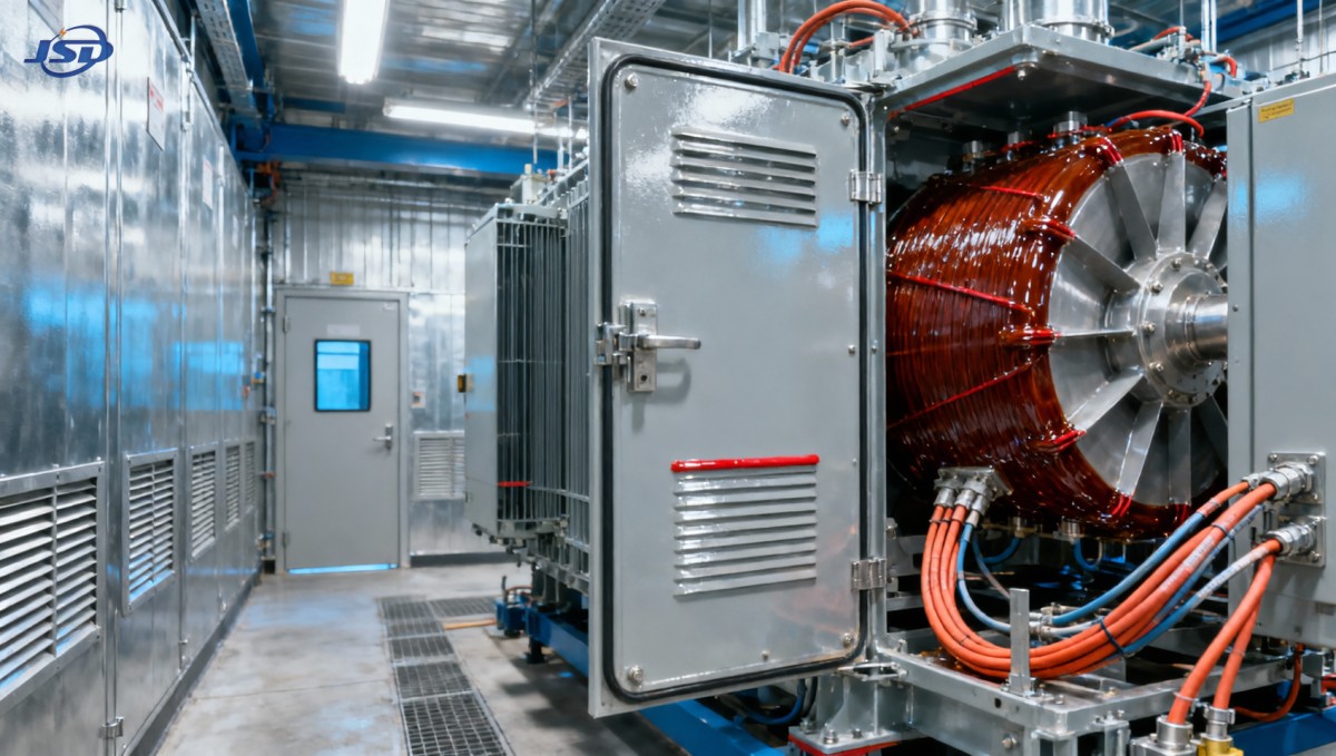
If the layout only works when maintenance doors remain closed or neighboring equipment is removed, treat that as a design warning. A slightly larger electrical room—or a different equipment orientation—may cost less than recurring production interruptions.
Give heat a defined route out of the room
A dry-type transformer transfers losses into the surrounding air. In a restricted room, the decisive issue is often not transformer size but whether that heat can escape during the hottest operating conditions.
Request guaranteed no-load and load losses for the proposed unit, together with the manufacturer’s cooling requirements. The ventilation assessment should include other heat sources in the room and evaluate losses at the expected operating load. For preliminary calculations, load losses generally vary approximately with the square of load fraction; detailed design should also account for temperature and harmonic effects.
The basic airflow relationship is:
Required airflow ≈ total heat to remove ÷ (air density × air specific heat × permitted air-temperature rise).
This relationship is useful for estimating airflow, but it is not a complete ventilation design. A mechanical engineer must also consider duct resistance, louvers, filters, fan performance, air distribution, and site conditions. A fan’s free-air rating does not prove it will deliver the required airflow through the installed system.
Where natural ventilation is feasible, arrange lower-level air entry and upper-level discharge to support buoyancy-driven flow, subject to the transformer’s specified airflow path. Mechanical ventilation may be necessary where room geometry, weather conditions, or heat density make natural airflow unreliable.
Avoid placing discharge air where it can return directly to the intake. Equally, do not assume the plant’s general HVAC system can absorb the additional heat without checking capacity. Dust filtration may protect the installation, but dirty filters introduce resistance and require maintenance.
Forced-air cooling can increase a transformer’s available capacity if the unit is designed and rated for it. It also introduces fans, controls, and a dependence on auxiliary power. If production relies on the forced-cooled rating, define what happens when a fan fails: alarm, load reduction, or protective action. Insulation temperature class alone is not permission to operate above the manufacturer’s specified conditions.
Resolve installation interfaces while changes are still inexpensive
Compact projects benefit from an interface review before purchase drawings are approved. Bring together the transformer supplier, electrical contractor, civil team, ventilation designer, and plant operations representative. Each sees a different potential obstruction.
Cables and busduct can determine the final footprint
Top-entry connections may appear convenient until they conflict with ventilation ductwork. Bottom entry can reduce overhead congestion but requires suitable trenches, floor openings, and moisture control. Check MV cable bending radii and termination requirements using the selected cable and accessory manufacturers’ data.
On the low-voltage side, high current can make cable quantity and termination space substantial. Busduct may offer a practical alternative, but its routing, supports, joint access, short-circuit withstand, and connection tolerances must be coordinated. Connections should not transfer unsupported mechanical loads to transformer terminals.
The delivery route deserves its own drawing
Measure the entire route: unloading position, gates, corridors, turns, floor transitions, doorway heights, and final placement area. Confirm shipping dimensions and mass, not just installed dimensions. Removable enclosure components may help only if the manufacturer approves the procedure.
Structural verification should cover permanent loading and temporary handling loads from skates, rollers, lifting equipment, or support points. Rigging must use approved lifting locations and a planned method. The shutdown window is the wrong time to discover that a floor opening cannot support the handling arrangement.
Earthing, noise, and protection are shared responsibilities
Coordinate enclosure and core earthing, secondary neutral arrangements, protection settings, and upstream and downstream fault duties. Transformer impedance affects both fault current and voltage regulation; selecting it solely to suit one objective can create problems elsewhere.
Where the room borders occupied workspaces, assess transformer sound and structure-borne vibration. Any vibration-control measures must remain compatible with anchoring, electrical bonding, and connection requirements. Protective temperature alarms and trips should be integrated into the plant’s operating procedures, not left as isolated panel indications.
Protect the shutdown schedule with a separate continuity plan
The installation schedule should identify which activities can happen while the plant remains operational. Civil preparation, ventilation installation, cable support work, and control-system preparation may be possible before the outage, provided safe segregation and approved work procedures are maintained.
For essential low-voltage loads, temporary energy storage can support a defined interruption strategy. One option is the 100kW/215kWh Mobile Trailer Energy Storage System, which combines a 100 kW PCS with 215 kWh of LiFePO4 battery capacity and a specified 400 V AC output. Its trailer-mounted arrangement can make it relevant to temporary plant services during a transformer changeover.
This is a continuity tool, not a direct replacement for a 20 kV supply. Engineers must confirm load compatibility, starting-current capability, earthing, protection, isolation, and transfer arrangements. Preventing unintended backfeed is essential. At a constant 100 kW load, 215 kWh represents a nominal energy-to-power ratio of 2.15 hours, not a guaranteed operating duration; usable capacity, conversion losses, reserve settings, temperature, and load behavior reduce or change practical runtime.
Select supported loads deliberately—perhaps controls, communications, or selected auxiliary services—rather than assuming the entire production line can remain online. Temporary battery equipment also requires an approved placement and fire-safety plan.
Commission the installation as a system
Commissioning should verify the transformer, its connections, protection, cooling, and operational interfaces together. Follow the manufacturer’s instructions and an approved test plan prepared by qualified personnel. Avoid applying generic high-voltage test procedures without confirming suitability for the equipment and connected accessories.
- Mechanical inspection: check transport damage, anchoring, cleanliness, clearances, ventilation openings, and connection torque records.
- Electrical verification: confirm earthing, tap position, ratio and vector group where specified, insulation checks, phase identification, and connection integrity.
- Functional testing: prove temperature monitoring, fan operation, alarms, trips, interlocks, and remote indications.
- Controlled energization: use an approved switching sequence, establish an exclusion zone, and check for abnormal sound, alarms, or unexpected indications.
- Loaded observation: monitor voltage, current balance, temperatures, and ventilation performance as operating load increases.
Arrange follow-up thermal inspection under representative load and safe conditions. An installation may pass initial checks yet reveal poor airflow or a problematic connection only after sustained production. Record baseline measurements so maintenance teams have something meaningful to compare later.
Make procurement deliver a usable installation
When evaluating suppliers, compare more than purchase price and enclosure dimensions. Ask for losses, drawings, cooling requirements, environmental suitability, test documentation, and clear limits on any proposed customization. A smaller unit is not a better project outcome if it creates uncertain operating conditions.
Jinshida Electric Power Technology Co., Ltd. focuses on the development, manufacture, and application of power transmission and distribution equipment. For a constrained plant project, early coordination with its technical team should center on the actual site layout, load profile, and installation interfaces rather than a nominal voltage specification alone.
Before releasing equipment for manufacture, secure coordinated drawings and named responsibility for ventilation, protection, structural work, and delivery access. Keep the final documentation package aligned with what is actually installed.
A successful 20 kV dry-type transformer installation leaves more than a clear floor around the equipment. It leaves safe access, dependable cooling, a credible maintenance route, and an operating team that understands the system. Resolving those details before delivery is what turns a tight space into a manageable project.

Get a Quote
Regardless of whether you require general advice or specific support, we are happy to help you.
Send Us Your Inquiry Today

Jinshida Electric remains committed to contributing to global energy development through professional manufacturing and superior service.