





How to calculate a 1000 kVA transformer's full-load current
A 1000 kVA transformer has a full-load current of approximately 1,443 A at 400 V on a three-phase supply. At 480 V, the current is approximately 1,203 A. Both values are correct: the current depends on the rated voltage and the number of phases, so the kVA rating alone cannot give you one universal amperage.
To calculate the current correctly, identify the voltage of the winding you are checking, establish whether the transformer is single-phase or three-phase, and use the corresponding formula. Calculate the primary and secondary currents separately because each winding operates at a different voltage.
The full-load current formula
Transformer capacity is normally expressed in kilovolt-amperes, or kVA. This is apparent power, which relates directly to voltage and current. For a balanced three-phase transformer, use:
Full-load line current, I = (kVA × 1,000) ÷ (√3 × V)
In this formula:
- I is the current in each line conductor, measured in amperes.
- kVA is the total three-phase transformer rating.
- V is the rated line-to-line voltage of the winding being calculated.
- √3 is approximately 1.732.
For a 1000 kVA unit, the formula becomes I = 1,000,000 ÷ (1.732 × V). You can also work directly in kVA and kV: I = 1,000 ÷ (1.732 × kV). Both versions produce amperes, provided you keep the units consistent.
For a single-phase transformer, use:
Full-load current, I = (kVA × 1,000) ÷ V
The single-phase equation does not include √3. At 400 V, a single-phase 1000 kVA transformer would therefore have a rated current of 2,500 A. That differs substantially from the three-phase result, which is why the phase arrangement must be established before calculating.
Worked example: a 1000 kVA, 11 kV/400 V transformer
Consider a three-phase transformer with a rated primary voltage of 11,000 V and a rated secondary voltage of 400 V. Its nameplate capacity is 1000 kVA.
Primary full-load current
Use the primary line-to-line voltage:
Iprimary = 1,000,000 ÷ (1.732 × 11,000) ≈ 52.5 A
This is the nominal rated primary line current. The high-voltage winding carries a relatively small current because it transfers power at a high voltage.
Secondary full-load current
Use the secondary line-to-line voltage:
Isecondary = 1,000,000 ÷ (1.732 × 400) ≈ 1,443 A
The secondary current is much higher because the transformer delivers approximately the same apparent power at a lower voltage. This explains why the low-voltage connections can require substantial busbars or parallel cables even when the primary current appears modest.
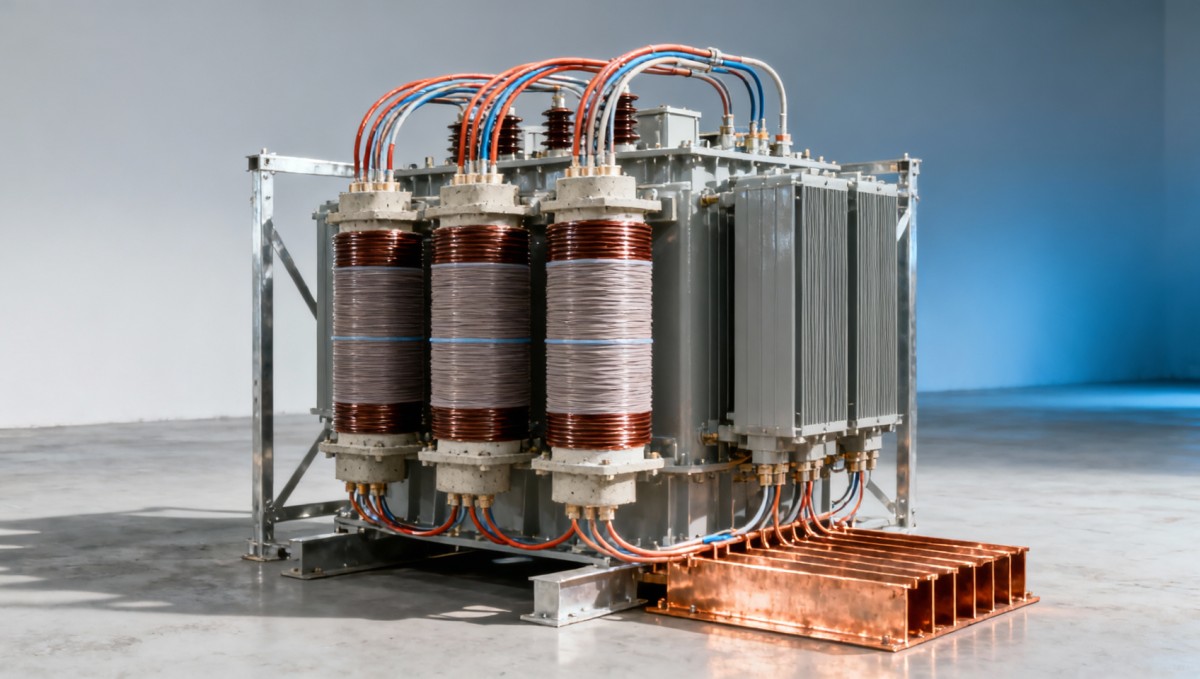
The calculated values describe rated line currents. Actual measured primary current also reflects transformer losses and magnetizing current, while secondary current follows the connected load. These equations establish the rated-current reference; they do not predict every operating measurement.
1000 kVA transformer current at common three-phase voltages
The following values use the same 1000 kVA rating and assume a balanced three-phase system. Each voltage is line-to-line, and the results are rounded.
Use the row corresponding to the winding you are assessing. An 11 kV/415 V transformer has a primary rated current of approximately 52.5 A and a secondary rated current of approximately 1,391 A.
The difference between 400 V and 415 V also matters. Although these voltages are close, they produce different current ratings. Use the actual nameplate voltage when preparing equipment schedules or evaluating an existing installation.
Why 230 V can give the wrong answer on a 400 V system
A three-phase, four-wire system may be described as 400/230 V. Here, 400 V is the voltage between two phases, while approximately 230 V is the voltage between a phase and neutral.
The three-phase formula requires 400 V. Inserting 230 V into that formula would give approximately 2,510 A, which is not the rated line current of a 1000 kVA, 400 V three-phase transformer.
For a balanced star-connected secondary, you can reach the correct result another way. Each phase carries one-third of the total apparent power, approximately 333.3 kVA. Dividing that phase power by the exact phase-to-neutral voltage, 400 ÷ √3, gives approximately 1,443 A. Small differences arise if you use the rounded value of 230 V.
Star and delta connections also affect the relationship between winding current and line current. In star, they are equal; in delta, line current is √3 times winding current under balanced conditions. The standard three-phase formula already returns line current, so no additional star-delta correction is needed when using total kVA and line-to-line voltage.
Does power factor change the calculation?
Power factor is not needed when calculating current from a transformer’s kVA rating. Apparent power already includes the voltage-current relationship.
At a power factor of 0.8, a load drawing 1000 kVA consumes:
Real power = 1000 × 0.8 = 800 kW
On a balanced 400 V three-phase supply, it still draws approximately 1,443 A. Multiplying the kVA rating by 0.8 before applying the current formula would understate the full-load current.
Power factor becomes necessary when the starting information is in kilowatts:
I = (kW × 1,000) ÷ (√3 × V × power factor)
For example, an 800 kW load at 0.8 power factor requires 1000 kVA. The same 800 kW at unity power factor requires 800 kVA and draws approximately 1,155 A at 400 V.
Do not add an efficiency factor to the nameplate kVA-to-current calculation. Efficiency is relevant when estimating input power and losses, or when converting a machine’s mechanical output into electrical demand. It is not an extra multiplier in the basic rated-current formula.
Rated current, operating current, and fault current serve different purposes
A transformer does not continuously deliver its full-load current. With a balanced 600 kVA load at 400 V, the current is approximately 866 A. This is 60% of the rated current, assuming the voltage remains at its rated value.
An unbalanced installation needs closer attention. A total load below 1000 kVA does not guarantee that every winding is within its current limit. Heavy single-phase loads can overload one phase while the others remain lightly loaded. Assess individual phase currents as well as total demand.
Short-circuit current is a separate calculation. A simplified estimate of the three-phase fault current at the secondary terminals is:
Fault current ≈ rated secondary current ÷ transformer impedance in per unit
If a hypothetical 1000 kVA, 400 V transformer has 6% impedance, this estimate gives 1,443 ÷ 0.06 ≈ 24,050 A. The example assumes a sufficiently strong upstream source and neglects other circuit impedances. An installation study must account for the source, cables, and other relevant contributions.
Transformer energization introduces another condition: magnetizing inrush. This brief current can exceed rated current substantially, so protection must distinguish energization from a fault. Neither fault duty nor inrush can be determined from kVA and voltage alone.
Using full-load current for cables and protection
The calculated current is a starting point for installation design. A secondary rated current of 1,443 A does not automatically establish the required cable size, breaker rating, or protection setting.
Cable capacity depends on conductor material, insulation temperature rating, installation method, ambient temperature, grouping, and terminal limitations. Parallel conductors also need an arrangement that supports appropriate current sharing. Voltage drop and short-circuit withstand require their own checks.
Breaker selection involves both normal current and fault conditions. Its interrupting capacity must suit the prospective fault current at its location, while its settings must coordinate with transformer characteristics and downstream protection. Simply choosing the next current rating above 1,443 A leaves these questions unanswered.
Applicable electrical rules may distinguish conductor sizing, overload protection, and short-circuit protection. Avoid applying one blanket percentage to all three. Establish the installation conditions and governing requirements before converting the calculated current into equipment selections.
Operating conditions can also limit usable capacity. High ambient temperature, restricted ventilation, altitude, and harmonic-rich loads may require an assessment of transformer loading. The nameplate current remains a reference, but the acceptable continuous operating load depends on the transformer’s design and service conditions.
When backup generation supplies the same installation
A building with a 1000 kVA transformer does not necessarily need a generator of the same rating. Transformer capacity may include spare capacity and loads that will be disconnected during an outage. Size backup generation around the loads that must remain energized, including motor starting and load-step requirements.
For selected essential circuits, a Silent Canopy Diesel Generator Set can be considered within its stated 50–500 kVA prime and 55–550 kVA standby ranges. Its three-phase, four-wire 230/400 V output is relevant to compatible low-voltage installations. Those ratings do not support supplying a fully loaded 1000 kVA transformer installation from one unit.
For comparison, 500 kVA at 400 V corresponds to approximately 722 A. The transfer arrangement and load schedule must keep demand within the selected generator’s electrical and operating limits. If the generator must energize a transformer, transformer inrush also becomes part of the sizing assessment.
What to establish before using the result
Start with the transformer nameplate and the system diagram. Record the rated kVA, phase arrangement, primary and secondary voltages, frequency, and relevant tap information. Use the winding voltage associated with the rated operating configuration; do not assume that every tap position permits identical current or capacity.
Then calculate each winding separately and label the result clearly—for example, “secondary full-load line current: 1,443 A at 400 V, three-phase.” Keeping the voltage and phase arrangement beside the amperage prevents that number from being reused incorrectly elsewhere.
Before selecting equipment, establish whether the task concerns normal loading, conductor capacity, overload protection, or short-circuit duty. Each uses the rated current differently. For the basic calculation, however, the rule is direct: divide 1,000,000 VA by √3 times the rated line-to-line voltage for a three-phase transformer, or by the rated winding voltage for a single-phase transformer.

Get a Quote
Regardless of whether you require general advice or specific support, we are happy to help you.
Send Us Your Inquiry Today

Jinshida Electric remains committed to contributing to global energy development through professional manufacturing and superior service.