





How harmonics affect 3-phase distribution transformer sizing
Harmonics can reduce the usable capacity of a 3 phase distribution transformer because distorted current produces additional winding and stray losses beyond those caused by an equivalent sinusoidal RMS current. When variable-frequency drives, UPS systems, or rectifiers dominate a load schedule, selecting a transformer solely from connected kVA can leave insufficient thermal margin—even when measured current remains below the nameplate rating.
The practical approach is to establish the harmonic current spectrum, calculate the resulting loss increase using transformer-specific data, and verify allowable loading under actual cooling and ambient conditions. A standard transformer may be suitable after derating; a harmonic-capable design may be preferable when distortion is substantial or continuous. There is no universal percentage allowance that applies to every installation.
Why rated RMS current does not guarantee rated temperature
A transformer’s conventional load-loss rating is established under specified test conditions, normally using sinusoidal current at rated frequency. Nonlinear equipment draws current in pulses or other distorted waveforms. Those currents contain a fundamental component plus harmonics at multiples of the supply frequency.
Three loss mechanisms matter when translating this distortion into a capacity limit:
- Winding resistance losses: The basic I2R component depends on total RMS current and winding resistance at operating temperature.
- Winding eddy-current losses: These increase strongly with harmonic frequency. Common engineering methods apply approximately harmonic-order-squared weighting within their stated assumptions.
- Other stray losses: Leakage flux produces additional heating in structural and conductive components. Their harmonic dependence differs from winding eddy losses and requires separate treatment.
Consequently, two transformers carrying the same RMS current can experience different heating when their current spectra differ. Two transformer designs supplying the same distorted load can also have different permissible capacities because conductor geometry, winding arrangement, and stray-flux control affect their losses.
Current harmonics primarily complicate load-loss assessment. Supply-voltage distortion can also affect core losses and flux waveform, so a current-only calculation is incomplete when voltage distortion is significant.
Measure the spectrum, not just the THD number
Current total harmonic distortion, THDI, describes harmonic RMS current relative to fundamental current:
THDI = √(Σ Ih2) / I1, for h ≥ 2.
The corresponding total current is IRMS = I1√(1 + THDI2), with THD expressed as a decimal. This identifies the increase in RMS current, but it does not fully describe frequency-dependent heating. A spectrum concentrated at lower orders can produce less winding eddy loss than one with the same THD concentrated at higher orders.
Use a power-quality analyzer at the transformer secondary or proposed connection point. Record individual harmonic currents in amperes, phase loading, neutral current, voltage distortion, and operating duration. Capture representative production cycles, UPS operating modes, and credible simultaneous loading rather than relying on one brief reading.
For a new installation, request equipment harmonic spectra at relevant load points and include any line reactors, filters, or active-front-end arrangements. “VFD load” is not a sufficient electrical specification: drive topology and input impedance materially change the current waveform.
Translate harmonic current into allowable loading
A useful intermediate quantity is the winding eddy-current harmonic loss factor:
FHL = Σ(h2Ih2) / ΣIh2.
Here, h is harmonic order, and the summations include the fundamental. For sinusoidal current, FHL equals 1. Higher-order components increase this factor rapidly. However, FHL is not a direct multiplier for total transformer losses: it applies to the winding eddy-loss component under the calculation method’s assumptions.
For preliminary understanding, a simplified winding-only expression is:
x ≈ √[(PDC,R + PEC,R) / (PDC,R + FHLPEC,R)].
In this expression, x is permissible RMS current as a fraction of rated current, PDC,R is rated-current winding resistance loss, and PEC,R is rated-frequency winding eddy loss. It assumes an unchanged harmonic spectrum as current scales and compares losses at a consistent reference temperature. It excludes other stray losses and is not a complete transformer rating calculation.
Its practical lesson is important: the same harmonic spectrum causes a larger derating where the original winding eddy-loss proportion is higher. Published total load loss alone cannot establish that proportion. Ask the manufacturer for the necessary loss breakdown or a guaranteed permissible loading assessment.
For final selection, use an applicable method such as IEEE C57.110, together with manufacturer design data and the relevant thermal limits. The assessment should address winding hot spots, other stray losses, cooling conditions, and any limitations of the chosen harmonic model.
A sizing example with explicitly assumed inputs
Suppose a proposed installation requires 800 kVA of sustained apparent power, already calculated from total RMS current. Assume a manufacturer’s harmonic and thermal assessment establishes an allowable loading factor of 0.85 for a candidate design under the specified conditions. The minimum nameplate capacity from that constraint is:
Srated,min = 800 / 0.85 ≈ 941 kVA.
A 1,000 kVA unit would then be a candidate for further verification, not an automatic approval. Voltage regulation, starting duty, future loading, impedance, and installation temperature still require checking. The assumed 0.85 factor is illustrative and must not be reused for another transformer or harmonic spectrum.
Avoid counting harmonics twice. When load kVA already uses total RMS current, harmonic current is already included in that electrical demand. Apply the thermal derating to it; do not first inflate the demand again using the same THD correction.
Neutral heating and delta windings need separate attention
In four-wire systems supplying single-phase nonlinear loads, triplen harmonics—particularly the third and its odd multiples—can add in the neutral instead of cancelling. Balanced fundamental phase currents therefore do not guarantee low neutral current.
A delta winding can provide a circulation path for zero-sequence triplen currents and limit their transfer into upstream line currents, depending on the connection and system arrangement. It does not eliminate the associated heating inside the transformer. Nor does a delta connection generally remove the fifth and seventh harmonics associated with balanced six-pulse rectifiers.
Specify the vector group, neutral terminal capability, and expected phase-to-neutral load composition. Evaluate neutral conductors, terminals, and switchgear alongside the transformer. Increasing transformer kVA alone does not establish that these components can withstand the resulting current.
Choosing between derating, a harmonic-capable design, and mitigation
Derating a standard transformer is reasonable when the spectrum is known, adequate capacity remains available, and the manufacturer confirms acceptable temperatures. The trade-off is that a larger unit may bring higher no-load losses, different impedance, and changed fault-current levels.
A K-rated or otherwise explicitly harmonic-capable transformer can be appropriate for sustained nonlinear loading. A K-factor designation concerns harmonic heating capability under its applicable rating system; it does not mean the transformer removes harmonics. Do not equate a K designation directly with an arbitrary THD limit, or assume that K-factor and another harmonic loss factor use identical normalization.
Harmonic mitigation can reduce the burden at its source. Reactors, suitable rectifier arrangements, or engineered filters may improve the spectrum enough to change transformer sizing. Their performance depends on operating conditions and network impedance; passive filters also require resonance assessment. Recalculate the transformer duty using the predicted or verified post-mitigation spectrum.
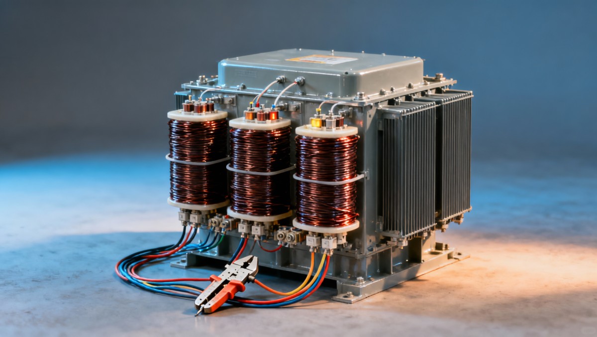
For an 11 kV/0.4 kV indoor application, the 11kV Three-Phase Cast Resin Dry-Type Distribution Transformer is one equipment option to assess. Its listed construction includes copper windings, epoxy-resin insulation, and temperature protection and control. These features support an indoor distribution application, but they do not establish a harmonic rating. Selection still requires confirmation of the particular unit’s loss breakdown, allowable spectrum, and thermal performance.
The product information also lists operation at 120% rated load with forced-air cooling. That statement should not be treated as an automatic harmonic allowance. Confirm its applicable ambient conditions, duration, temperature-rise limits, fan requirements, and suitability for the actual distorted current.
Standards and specifications that make the decision defensible
IEEE C57.110 provides methods for evaluating transformer capability with nonsinusoidal load currents within its scope. For dry-type equipment, IEC 60076-11 addresses relevant transformer requirements, while IEC 60076-12 provides loading guidance. Identify the applicable editions and contractual requirements rather than accepting a broad “IEC compliant” statement as evidence of harmonic suitability.
IEEE 519 addresses harmonic control at the defined point of common coupling. Compliance there does not prove that an individual downstream transformer can carry its full nameplate load without excessive heating. Network harmonic limits and transformer thermal capability answer different questions.
A technically useful purchase specification should require:
- A defined duty: supply frequency, voltage, harmonic currents by order and phase, maximum RMS demand, load profile, and expected future nonlinear loading.
- Installation conditions: ambient temperature, altitude, enclosure arrangement, ventilation, and whether forced cooling is essential for normal duty.
- A verifiable capacity statement: guaranteed continuous kVA for the submitted spectrum, including the calculation basis, winding temperature rise, and hot-spot assessment.
- Supporting design information: relevant load-loss components or a documented manufacturer calculation, plus neutral capability and winding connection.
- Acceptance arrangements: applicable routine and temperature-rise test evidence, with agreement on how harmonic-duty performance will be demonstrated.
After commissioning, compare measured spectra and loading against the design inputs. Investigate sustained temperature increases alongside ambient conditions, ventilation, phase imbalance, and fan status rather than attributing every hot transformer to harmonics. If additional drives or UPS capacity are connected later, reassess the harmonic duty even when aggregate kVA still appears below the original nameplate rating.

Get a Quote
Regardless of whether you require general advice or specific support, we are happy to help you.
Send Us Your Inquiry Today

Jinshida Electric remains committed to contributing to global energy development through professional manufacturing and superior service.