





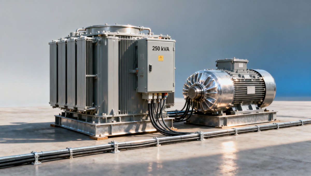
Can a 250 kVA transformer handle your largest motor's starting load?
Can a 250 kVA transformer handle your largest motor's starting load?
A motor’s running load may fit comfortably within a 250 kVA transformer’s rating, but starting it can tell a different story. High starting current can cause voltage dips, reduce starting torque, and disrupt other connected equipment. The question is not simply whether the transformer can supply the motor, but whether it can support acceleration under actual system conditions.
The answer can be yes—but the transformer rating alone cannot establish that. You need the motor’s starting characteristics, transformer impedance, upstream supply strength, cable impedance, and the loads already operating. A short starting event above rated transformer current is not automatically unacceptable; a prolonged start with inadequate torque can be.
Start with current, not just motor power
For a three-phase transformer, rated secondary current is calculated from apparent power and line-to-line voltage:
Rated current = transformer kVA × 1,000 ÷ (√3 × secondary voltage)
At 400 V, a 250 kVA transformer supplies approximately 361 A at rated load. At 480 V, the corresponding current is approximately 301 A. These are continuous-rating reference points, not guaranteed motor-starting limits.
Motor nameplate kW usually describes mechanical output. Electrical input is higher because of losses, and apparent power also depends on power factor. For a preliminary running-load calculation:
Motor running kVA = output kW ÷ (efficiency × running power factor)
Starting demand must be evaluated separately. Obtain locked-rotor current, the manufacturer’s starting-current ratio, or applicable nameplate starting data. Direct-on-line induction motors can draw several times full-load current, but a generic multiplier is not a substitute for the selected motor’s data.
Also distinguish motor starting current from transformer energization inrush. They are different events. If the transformer is energized and a large motor starts immediately afterward, the switching sequence deserves separate review.
A worked screening example
Consider an illustrative 75 kW, 400 V, three-phase motor. Assume 94% efficiency, 0.86 running power factor, and direct-on-line starting current equal to six times full-load current. These are calculation assumptions, not specifications for a particular product.
- Running apparent power: 75 ÷ (0.94 × 0.86) ≈ 92.8 kVA.
- Full-load current: 92,800 ÷ (√3 × 400) ≈ 134 A.
- Starting current at rated terminal voltage: 6 × 134 ≈ 804 A.
- Starting apparent power at rated voltage: √3 × 400 × 804 ÷ 1,000 ≈ 557 kVA.
The motor’s running demand occupies only about 37% of the transformer rating, yet its initial starting demand is more than twice that rating. This does not mean a 557 kVA transformer is required. It means voltage performance and acceleration must be checked rather than inferred from continuous capacity.
For a rough transformer-only screen, multiply starting current in per-unit of transformer rated current by transformer impedance in per-unit. With an assumed 5% impedance:
Impedance-drop screening value ≈ (804 ÷ 361) × 0.05 ≈ 0.111, or 11.1%
Treat this as a warning indicator, not a predicted terminal-voltage dip. It represents an approximate impedance-drop magnitude using rated-voltage starting current. Actual voltage depends on resistance and reactance, starting power factor, upstream impedance, cables, existing loads, and the way motor current changes as voltage falls. A circuit calculation or motor-starting simulation is needed for a defensible result.
Why voltage dip can become an acceleration problem
A motor does not merely need current; it needs enough accelerating torque throughout the run-up. For an induction motor at a given frequency and slip, electromagnetic torque varies approximately with the square of applied voltage. At 85% terminal voltage, torque is roughly 72% of its corresponding full-voltage value.
That reduction may be manageable for an unloaded machine. It can be decisive for a loaded conveyor, compressor, or high-inertia load. If motor torque barely exceeds load torque, acceleration takes longer. The extended high-current period then increases heating and can operate protection before the motor reaches speed.
There is no universal acceptable voltage-dip percentage for every installation. Check the motor’s torque-speed curve against the driven equipment’s load-torque curve, then check the ride-through limits of contactors, controls, drives, and other connected equipment. A motor may start successfully while the rest of the process trips.
The rest of the electrical system changes the answer
Transformer impedance matters because it contributes to source stiffness. For otherwise comparable transformers, lower impedance generally reduces the transformer’s contribution to starting voltage drop. However, it also increases available fault current. Selecting lower impedance without checking switchgear interrupting ratings and protection coordination can exchange one problem for another.
The upstream network matters just as much. A strong utility connection and a generator-fed installation can behave very differently with the same transformer and motor. For generator supplies, alternator transient characteristics, excitation response, and engine performance may govern the result.
Long secondary cables add another drop between the transformer terminals and the motor. A satisfactory voltage at the main board does not prove satisfactory voltage at the motor terminals. Include cable length, conductor material, cross-section, installation conditions, and operating temperature in the model.
Existing loads should be represented by their real and reactive demand, not simply subtracted from 250 kVA to create a “starting allowance.” Running motors may change current during the dip, while some electronic loads attempt to maintain power. Automatic restart after a supply interruption can also produce a worse condition than the normal operating sequence.
Choose a starting method that preserves enough torque
When direct-on-line starting is marginal, changing the starting method may be more effective than immediately increasing transformer capacity. The correct choice depends on the driven load.
A drive can make a previously difficult start practical, but its input demand must be assessed from drive data rather than the motor’s direct-on-line locked-rotor current. Conversely, a soft starter is not a guarantee that a heavily loaded motor will accelerate on a weak supply.
Protecting controls is different from supplying the motor
Sometimes the immediate process risk is a control-system reset rather than failure of the main motor to start. A properly engineered UPS or battery-backed control supply can address that separate problem. For light-commercial auxiliary backup, a 51.2V Wall-mounted LiFePO4 Energy Storage Battery provides 5.12 kWh nominal storage with CAN/RS485 communication, subject to compatible inverter and system design.
It should not be treated as direct starting support for a large industrial motor. Its stated 100 A maximum discharge current corresponds to approximately 5.12 kW DC at nominal voltage, before conversion losses. Battery energy capacity, inverter surge capability, and motor-starting kVA are different constraints.
What to verify before approving the transformer
A detailed motor-starting study becomes particularly useful when the preliminary voltage-drop screen is close to equipment limits, the motor starts under load, acceleration is long, starts are frequent, or several machines may restart together. Use the lowest credible supply voltage and the heaviest credible operating load—not only the most convenient normal condition.
The evaluation package should include:
- Transformer data: rated voltages, impedance and tolerance, losses or resistance/reactance data, tap position, cooling, and site derating conditions.
- Motor and load data: full-load and locked-rotor current, torque-speed curves, inertia, starting method, acceleration time, and starts per hour.
- Network data: upstream source impedance, feeder details, operating loads, restart sequence, and sensitive-equipment voltage limits.
- Protection data: breaker and relay curves, overload settings, contactor limits, and motor thermal withstand information.
Jinshida Electric Power Technology Co., Ltd. focuses on the R&D, manufacturing, and application of transmission and distribution equipment. For a motor-duty transformer assessment, that manufacturing and application scope is most relevant when it produces clear project documentation: proposed impedance, applicable test information, operating-condition assumptions, and the interface data needed by the system designer.
Approve a 250 kVA transformer only when continuous loading, minimum starting voltage, acceleration time, thermal duty, and protection coordination are acceptable together. If the assessment fails, compare a revised starting method, unloaded starting, staged restart, feeder improvements, or a larger transformer. The deciding evidence is successful acceleration without unacceptable disturbance—not simply a motor kW figure below the transformer’s kVA rating.

Get a Quote
Regardless of whether you require general advice or specific support, we are happy to help you.
Send Us Your Inquiry Today

Jinshida Electric remains committed to contributing to global energy development through professional manufacturing and superior service.