





How Hermetically Sealed Power Distribution Transformers Control Internal Pressure
How Hermetically Sealed Power Distribution Transformers Control Internal Pressure
A hermetically sealed power distribution transformer is engineered to maintain stable internal pressure while isolating insulating oil from moisture, oxygen, and external contaminants. For technical evaluators, understanding this pressure-control mechanism is essential when assessing transformer reliability, insulation aging, maintenance requirements, and long-term performance in demanding grid, industrial, and renewable energy applications.
The central idea is simple, but its engineering implications are not: transformer oil expands when heated and contracts when cooled. If the tank cannot accommodate that changing volume without drawing in outside air, the insulation system gradually becomes exposed to oxygen and water vapor. A sealed design addresses this issue by allowing the tank structure to absorb normal oil-volume variation while keeping the liquid insulation system closed to the atmosphere.
Pressure Changes Begin with Oil Temperature
In an oil-immersed distribution transformer, load losses and ambient conditions change the temperature of the windings, core, and dielectric liquid. As oil temperature rises, its volume increases. As the transformer cools, the volume decreases. This is a normal operating cycle, not necessarily a fault condition. The question for design review is how the transformer manages that movement.
A conventional conservator-type transformer usually handles expansion through an oil reservoir that is connected to the main tank. Depending on the arrangement, the transformer may use a breather system to reduce moisture ingress as air moves in and out. A hermetically sealed power distribution transformer follows a different approach: there is no routine atmospheric exchange through a breather. Instead, oil expansion and contraction are managed inside a sealed system.
This distinction matters because air exchange is not benign. Oxygen contributes to oil oxidation, while moisture can reduce dielectric strength and accelerate degradation of cellulose insulation. Over a long service period, these effects can influence oil quality, insulation condition, and the maintenance work required to keep the unit in service. Sealing does not eliminate every aging mechanism, but it removes a common route for contamination.
The Flexible Tank Principle
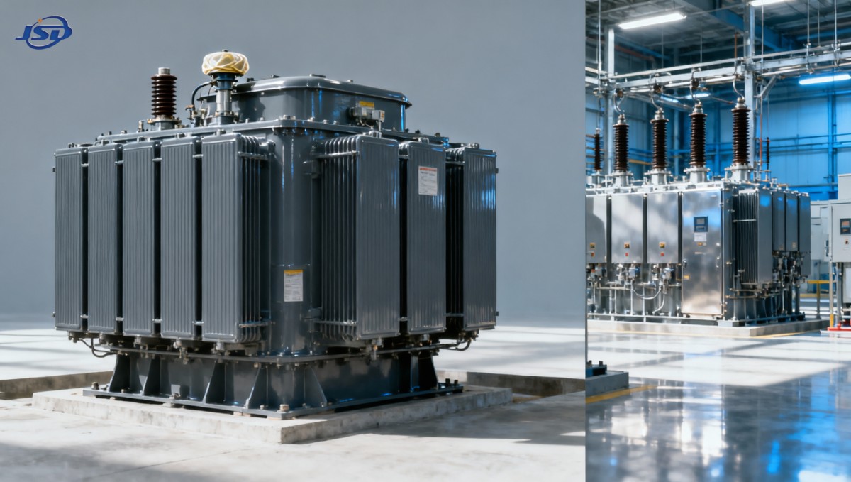
Most sealed oil-filled distribution transformers control internal pressure through a flexible tank wall, often formed with corrugated panels or fins. These corrugations serve two practical purposes. They increase the surface area available for cooling, and they flex slightly as the oil volume changes. When the transformer heats up, the corrugated walls move outward. When it cools, they move inward.
The tank is therefore not merely a container. It is an active part of the pressure-management system. Properly designed corrugations must provide sufficient elastic movement for the expected oil-volume change over the specified operating temperature range, while maintaining mechanical strength during transport, installation, short-circuit events, and years of thermal cycling.
The internal condition is often described as having positive or negative pressure relative to ambient pressure, depending on temperature and filling condition. The goal is not to hold one fixed pressure value at all times. The goal is to keep pressure within the tank’s allowable operating range without admitting external air or overstressing the enclosure. Evaluators should be cautious when a supplier describes a unit simply as “vacuum sealed” or “pressure sealed” without defining the intended operating limits and test method.
Why Initial Oil Filling Is Critical
Pressure behavior is influenced well before commissioning. During manufacturing, the active part must be dried, the tank must be properly assembled, and the oil filling process must control residual moisture and entrapped gas. Vacuum oil filling is commonly used to help reduce retained air in the insulation system. The final filling temperature, oil level, gas space assumptions, and ambient design range all affect how the tank behaves later in the field.
An excessively high filling condition can leave too little expansion capacity during high-temperature operation. An excessively low filling condition may create unacceptable internal vacuum during cold conditions or reduce dielectric margins around the active part. These are not details that can be judged from nameplate data alone. They require review of the manufacturer’s design basis, filling procedure, tank geometry, and applicable project specification.
What Actually Protects the Insulation System
The value of hermetic sealing lies primarily in contamination control. When a transformer breathes, it repeatedly exposes its oil preservation system to ambient humidity. Breathers and desiccant systems can manage this exposure, but they introduce inspection and maintenance requirements. A fully sealed tank avoids routine intake of humid air, which can be particularly useful in coastal areas, humid industrial zones, remote substations, and locations where maintenance access is limited.
However, sealing should not be treated as a substitute for sound insulation design. Oil quality, paper quality, drying performance, thermal design, winding clamping, bushing integrity, and protection coordination remain consequential. A sealed transformer with poor tank weld quality or inadequate bushing sealing will not deliver the intended benefit. In practice, long-term performance depends on the complete boundary of the sealed system, not just the presence of corrugated walls.
For this reason, factory inspection should include more than a visual check of the tank. Depending on the agreed standard and contract requirements, technical teams may review routine test records, leak testing arrangements, pressure or vacuum holding procedures, oil handling controls, and the traceability of seals and bushings. The exact acceptance criteria should be agreed against the governing IEC, ANSI/IEEE, utility, or local project requirements rather than assumed to be identical across markets.
Pressure Relief Is Still Necessary
A sealed transformer is designed to manage normal thermal pressure changes; it is not designed to contain every abnormal internal event. Serious internal faults can generate gas and a rapid pressure rise. This is why pressure-relief devices, where specified by design and application, remain relevant. Their purpose is emergency protection of the tank, not routine pressure balancing.
Technical evaluations should separate these two functions. Corrugated tank movement accommodates ordinary expansion and contraction. A pressure-relief device responds to abnormal overpressure. Confusing the two can lead to an incomplete protection review. The presence of a relief device does not prove that the transformer has adequate thermal expansion capacity, and a well-designed flexible tank does not remove the need to assess fault-pressure protection.
Questions Worth Asking During Technical Evaluation
The most useful technical questions are specific. Rather than asking whether a transformer is “hermetically sealed,” ask how the seal is maintained over the stated temperature range and service life. Ask whether the design uses a corrugated tank, a gas cushion, or another expansion arrangement. Confirm whether the unit is intended for indoor or outdoor installation, and whether altitude, solar loading, ambient temperature extremes, or frequent overload cycles change the design assumptions.
- What ambient temperature range and oil-temperature conditions were used to calculate expansion capacity?
- What leak-test or pressure-holding procedure is applied to the completed tank?
- How are bushings, valves, gauges, welds, and cable-box interfaces sealed?
- Is a pressure-relief device fitted, and what is its intended protective function?
- Are transport conditions likely to require temporary pressure controls or special inspection after delivery?
- Which edition of the applicable transformer standard and purchaser specification governs routine and type-test expectations?
These questions are especially relevant for renewable-energy collector systems and industrial loads with fluctuating demand. A transformer that experiences repeated thermal cycling may still operate within rating, yet its tank and sealing interfaces will see more frequent movement than a lightly loaded unit in a stable network. That does not automatically make a sealed design unsuitable; it means the load profile should be part of the mechanical and thermal review.
Do Not Apply Oil-Filled Pressure Logic to Dry-Type Transformers
A common specification mistake is to transfer requirements for liquid-filled sealed transformers directly to dry-type equipment. Cast resin dry-type transformers do not rely on mineral oil expansion or an oil tank pressure-control system. Their insulation and cooling approach is different: windings are insulated with solid materials such as epoxy resin and cooled by air, with thermal monitoring and ventilation arrangements becoming central considerations.
For indoor substations, commercial facilities, public infrastructure, and locations where fire performance or oil containment is a major concern, the engineering comparison may lead to a dry-type option rather than a hermetically sealed oil-filled unit. For example, the 20kV Three-Phase Cast Resin Dry-Type Distribution Transformer is designed for 20 kV distribution applications and uses air or solid insulation rather than liquid coolant. Its SCB10-12 configuration is available across a broad capacity range, with project-specific voltage, protection, enclosure, and cooling requirements requiring confirmation during design review.
This is not a question of one technology being universally superior. Sealed oil-filled transformers are often selected for compact outdoor distribution and applications where liquid insulation is appropriate. Cast resin units may be preferred where indoor location, fire behavior, and reduced liquid-related risk govern the decision. The evaluator should compare installation conditions, losses, ventilation, environmental exposure, fault protection, maintenance capability, and applicable code requirements before selecting the insulation system.
Where Pressure-Control Designs Can Fail
The failure modes are usually more practical than mysterious. A damaged corrugated panel can reduce expansion capability or create a leak path. Poor weld quality can allow slow air ingress that is difficult to notice during early service. Aging gasket materials, improperly tightened bolted joints, and compromised bushing interfaces can all undermine hermetic integrity. Mechanical damage during handling deserves attention as well, particularly when transformers are shipped over long distances or moved with unsuitable lifting practices.
Field symptoms may not always appear as an immediate outage. A slow leak may first show up as reduced oil level, oil staining, recurring gas-pressure concerns, or oil-condition trends that warrant investigation. The correct response depends on the design and observed condition. It may involve inspection, leak localization, oil testing, seal replacement, or manufacturer guidance. Simply adding oil without identifying the reason for the loss can conceal the underlying problem and alter the intended fill condition.
A Better Basis for Selecting the Transformer
For a hermetically sealed power distribution transformer, pressure control should be assessed as part of insulation preservation and tank reliability, not as an isolated feature on a datasheet. The right review combines electrical rating, thermal duty, ambient range, installation environment, sealing details, protection devices, manufacturing controls, and the standard named in the purchase specification.
Jinshida Electric Power Technology Co., Ltd. approaches distribution equipment through that broader engineering lens. Its work in the research, manufacturing, and application of transmission and distribution equipment is supported by technical teams, controlled manufacturing processes, and quality management practices intended to support grid construction, industrial facilities, renewable-energy projects, and infrastructure systems. For evaluators, the productive next step is to align the transformer design with the actual operating envelope: voltage and capacity are only the starting point; temperature cycling, sealing expectations, installation constraints, and verification requirements determine whether the selected design is genuinely fit for service.

Get a Quote
Regardless of whether you require general advice or specific support, we are happy to help you.
Send Us Your Inquiry Today

Jinshida Electric remains committed to contributing to global energy development through professional manufacturing and superior service.