






Harmonic-rich loads can turn a transformer’s nameplate rating into an incomplete measure of suitability. Technical evaluators should prioritize verified thermal performance under the actual load spectrum.
For teams selecting a three phase high voltage transformer supplier, the critical questions concern harmonic-related losses, thermal margins, insulation performance, and reliable operation under nonlinear loads.
This article explains how to assess supplier capabilities, review design and test documentation, and translate load-spectrum data into practical procurement criteria for demanding applications.
The strongest proposal connects your operating conditions to calculated losses, winding temperatures, and enforceable guarantees. A larger kVA rating alone does not establish harmonic suitability.
What Load Information Should You Give Suppliers Before Requesting a Quote?
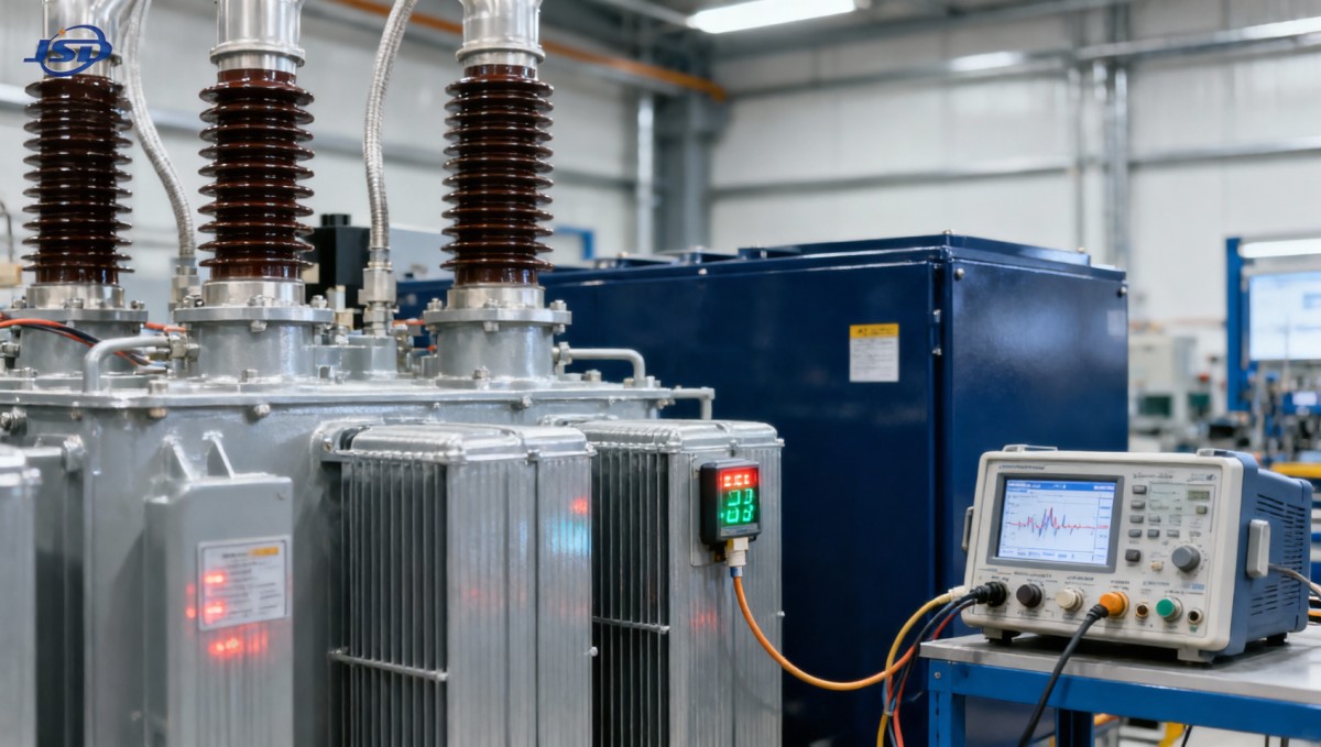
Start with a shared technical specification. Without consistent load data, suppliers may price different assumptions, making apparently comparable transformer quotations technically incompatible and difficult to evaluate.
Identify the nonlinear equipment: variable-frequency drives, rectifiers, uninterruptible power supplies, electric vehicle chargers, or inverter-connected generation. Record their operating schedules and expected simultaneous loading.
Request current harmonic magnitudes by order and phase at the proposed transformer terminals. Include fundamental current, RMS current, voltage distortion, power factor, and phase imbalance.
Current total harmonic distortion is useful for screening, but it cannot replace the spectrum. Similar distortion percentages can produce different additional losses when harmonic orders differ.
Measurements should cover representative production cycles, peak demand, light loading, and unusual operating modes. Document measurement locations, instrumentation, aggregation intervals, and whether readings include existing mitigation.
For new installations, use equipment manufacturers’ harmonic data and a system study. Require suppliers to identify assumptions that need confirmation during commissioning measurements or acceptance testing.
Include ambient temperature, altitude, installation clearances, enclosure conditions, and future expansion. State whether the transformer serves continuous duty, intermittent production, bidirectional power flow, or frequent overloads.
Does the Supplier Calculate Harmonic Losses or Merely Add Capacity?
Harmonic currents increase RMS current and frequency-dependent losses. Winding eddy losses and stray losses can rise substantially even when fundamental-frequency loading appears comfortably below nameplate capacity.
Ask for separate estimates of no-load loss, winding resistance loss, winding eddy loss, and other stray loss. The calculation should use your specified harmonic spectrum.
A supplier should explain the calculation method, frequency assumptions, conductor arrangement, and treatment of structural heating. A generic statement about “low losses” provides insufficient evidence.
Consider a simplified spectrum with fundamental current normalized to 1.00, fifth-harmonic current of 0.20, and seventh-harmonic current of 0.10, with other harmonics omitted for illustration.
RMS current becomes approximately 1.025 times fundamental current. Resistance-related winding losses therefore increase approximately 5%, assuming unchanged resistance and comparing against the same fundamental-current operating point.
Under a simplified square-of-frequency weighting, the harmonic loss factor for winding eddy losses is approximately 2.37. This illustrates why RMS current alone can understate heating.
That factor does not multiply total transformer losses. Actual results depend on baseline eddy losses, conductor geometry, frequency effects, and the supplier’s validated calculation approach.
Upsizing may be appropriate, but require its technical basis. Compare additional capacity with winding-design changes, harmonic mitigation, and operating restrictions using the same duty assumptions.
What Proves Adequate Thermal Margin and Insulation Life?
The decisive question is whether winding hot-spot temperatures remain acceptable throughout the specified duty cycle. Average temperature rise and top-oil temperature cannot independently establish this.
Request predicted top-oil temperature, winding temperature rise, hot-spot temperature, and insulation aging under normal loading, worst-case harmonics, highest ambient temperature, and planned overload events or cycles.
Ask how the thermal model was validated. Relevant evidence includes temperature-rise tests, design-family experience, and calculations that clearly explain differences between tested and proposed units.
Standard temperature-rise testing typically does not reproduce every project’s harmonic spectrum. Suppliers should explain how measured results support their harmonic-duty predictions and identify remaining uncertainty.
Oil type, paper insulation, cooling arrangement, and moisture control affect thermal performance and aging. Evaluate these together rather than treating fluid selection as an independent guarantee.
Require dielectric ratings appropriate to system voltage, grounding, and surge exposure. Harmonic-related heating concerns do not replace checks on insulation coordination and applicable dielectric test requirements.
Monitoring should match the operating risk. Specify relevant temperature sensors, alarm thresholds, trip settings, and maintenance requirements, especially where unattended operation or production continuity is important.
Which Electrical Design Details Affect Harmonic Compatibility?
Review vector group, grounding arrangement, neutral capacity, impedance, and winding construction. Each affects system behavior, but no single feature establishes suitability for all nonlinear loads.
Triplen harmonics can become significant with single-phase nonlinear loads. Depending on winding connections and grounding, they may load neutrals or circulate within delta windings significantly.
A delta winding can influence zero-sequence harmonic paths, but it does not eliminate all harmonic losses. Ask suppliers to explain expected currents within each winding.
Transformer impedance affects voltage regulation, fault current, and interactions with converters. Evaluate it alongside cable impedance, upstream network strength, and the proposed protection coordination study.
Power-factor correction capacitors can create resonance with network inductance. Review capacitor banks, filters, and switching states through a harmonic study before approving the transformer specification.
For photovoltaic or wind applications, confirm reverse-power duty, converter behavior, voltage-control requirements, and tapping strategy. Distribution service and generator step-up service can require different design assumptions.
Request explicit compatibility limits for voltage distortion and current harmonics. Those limits should identify measurement locations and operating conditions, enabling meaningful commissioning checks and warranty discussions.
How Should You Evaluate a 30kV/0.4kV Product Offering?
For a project using 30kV distribution and 400V utilization voltages, Jinshida Electric’s 30kV/0.4kV Oil-Immersed Power Distribution Transformer provides a product option to assess against the specified duty.
The supplied product information lists S-M models, copper windings, and capacities from 500 to 1600kVA. These establish an initial shortlist, not proof of harmonic capability.
For a 1000kVA, 400V three-phase unit, rated line current is approximately 1,443A. Compare this with calculated RMS demand before evaluating additional harmonic losses and thermal margins.
The stated efficiency exceeds 99%, but request guaranteed no-load and load losses, reference temperature, and the operating point used. Efficiency changes with loading and waveform.
The listing references FR3 vegetable oil and ONAN cooling. Ask the supplier to reconcile the fluid specification with the applicable cooling designation on the final datasheet.
For natural ester designs, verify fluid properties, thermal assumptions, material compatibility, and applicable fire-performance documentation. Fluid selection alone does not establish a permissible operating temperature.
The advertised overload capability reaches 150% for up to two hours, subject to oil-temperature monitoring at 95°C or below. Treat this as requiring project-specific verification.
Starting load, ambient conditions, harmonic content, hot-spot temperature, and acceptable aging determine overload suitability. An oil-temperature threshold alone cannot confirm safe operation under that duty.
Likewise, verify the scope of the stated IP65 rating and service-life claims. Identify covered enclosures, required maintenance, operating assumptions, and contractual guarantees before relying on them.
Which Standards and Test Documents Actually Support the Offer?
Ask for an agreed standards schedule covering design, testing, loading, and installation. Listing many standard names without editions or applicability creates ambiguity rather than confidence.
IEC 60076 provides relevant power-transformer requirements, while IEC 60076-7 addresses loading guidance for mineral-oil-immersed transformers. Confirm how guidance applies if the proposed fluid differs materially.
For applicable IEEE-based evaluations, IEEE C57.110 addresses transformer capability when supplying nonsinusoidal load currents. Require suppliers to identify the chosen method and its design limitations.
IEEE 519 addresses harmonic control in power systems, including limits at the point of common coupling. Compliance there does not independently prove transformer thermal suitability.
Distinguish management-system certification from product evidence. ISO 9001 concerns quality management; it does not demonstrate that a particular transformer meets your harmonic-duty specification or thermal guarantees.
Request applicable routine, type, and special test records. Review ratio, losses, impedance, dielectric performance, temperature rise, and other agreed checks against the proposed transformer’s design.
For European efficiency claims, verify applicable requirements under Commission Regulation (EU) No 548/2014, as amended. Product-listing references should be checked against current requirements and project scope.
Any claimed third-party certification should identify the issuing organization, covered model, test scope, and validity. A certification name without supporting documentation carries limited evaluation value.
How Can You Compare Supplier Proposals Fairly?
Give every bidder the same load spectrum and duty cycle. Require a compliance matrix distinguishing guaranteed performance, calculated predictions, supporting test evidence, and unresolved exceptions.
Weight thermal capability and documented compliance heavily when production reliability matters. Price should be compared only after offers meet the same mandatory technical requirements consistently.
Evaluate annual loss costs using the expected loading profile and harmonic conditions. Include cooling auxiliaries where applicable, maintenance obligations, and any required external mitigation equipment.
Ask for relevant operating references with comparable converter loads, ambient conditions, and service duration. Reference installations support confidence but cannot substitute for your project’s calculations.
Jinshida Electric’s stated focus on power-equipment development, manufacturing, and quality management provides business context. Technical acceptance should still depend on documented performance for the proposed configuration.
What Should Be Written into the Purchase Specification?
Attach the agreed harmonic spectrum, loading profile, environmental conditions, voltage requirements, and cooling configuration to the contract. Define how material deviations trigger reassessment or corrective action.
Specify guaranteed losses, permissible temperature limits, overload conditions, required monitoring, and applicable tests. Clearly distinguish measurable acceptance requirements from predictions that cannot be directly factory-verified.
Plan commissioning measurements under representative operating conditions. Compare measured currents, voltage distortion, loading, and temperatures with the agreed design envelope, accounting for sensor and measurement limitations.
Define responsibilities if actual loads exceed the declared spectrum. Possible responses include operating limits, additional mitigation, revised cooling, or a new engineering assessment before continued operation.
Select a three phase high voltage transformer supplier that can connect load data to defensible design decisions. Documented thermal margins and clear guarantees make procurement decisions stronger.
The final judgment should rest on verified suitability for your operating duty. Nameplate capacity, efficiency claims, and certifications become useful when supported by applicable engineering evidence.
