





Choosing a Power Transformer Manufacturer for High-Fault-Level Networks
Choosing a Power Transformer Manufacturer for High-Fault-Level Networks
In high-fault-level networks, choosing an electrical power transformer manufacturer requires more than comparing ratings and efficiency figures. Technical evaluators must examine short-circuit withstand capability, impedance tolerances, protection coordination, and the evidence behind design claims. A transformer that meets routine operating requirements may still be vulnerable to severe thermal and mechanical stresses during faults. The engineering criteria, test documentation, and manufacturing controls discussed here help distinguish a capable supplier from a high-risk choice for demanding grid, industrial, and infrastructure applications.
The key procurement question is not simply whether a transformer complies with a standard. It is whether the proposed design can withstand the fault duty at its installation point—and whether the manufacturer can demonstrate that capability before the purchase order becomes difficult to change.
Define the fault duty before comparing suppliers
“High fault level” is not a complete design requirement. A utility may quote available short-circuit power at the medium-voltage connection, while the transformer supplier discusses fault current at the low-voltage terminals. Both values matter, but they describe different parts of the system. Source impedance, transformer impedance, cable impedance, and contributions from other connected equipment determine the actual duty.
Give each bidder the same network study assumptions. These should cover maximum and minimum source conditions, system X/R ratio, earthing arrangements, operating configurations, and primary and backup protection clearing times. Include future reinforcement where it is already planned. A transformer selected for today’s radial supply may face a different duty after a bus tie closes or another transformer is connected in parallel.
Industrial motors can contribute current during the initial fault period. Renewable generation also needs attention, although inverter-based contribution depends on converter controls and protection rather than behaving like a conventional rotating machine. The study should represent the connected equipment, not assume one generic contribution factor.
Ask bidders to state the symmetrical RMS current, asymmetrical peak current, and fault duration used in their assessment. An offer that says only “short-circuit resistant” leaves the most important boundary conditions unresolved.
Impedance is a system decision, not a catalogue preference
Transformer impedance limits downstream fault current, but increasing it is not a free improvement. Higher impedance generally increases voltage drop under load and can complicate motor starting or voltage-sensitive processes. Lower impedance improves voltage regulation but may increase demands on switchgear, busbars, cables, and the transformer itself.
Consider an illustrative calculation, not a product rating: a 1,000 kVA, 400 V three-phase transformer has a rated secondary current of approximately 1,443 A. With 6% impedance and an effectively infinite upstream source, the approximate symmetrical terminal fault current is 24 kA. Actual results require source impedance, voltage factors, impedance tolerances, and other contributions. The calculation is useful for screening; it is not a substitute for a network study.
The guaranteed impedance tolerance matters as much as the nominal figure. A lower actual impedance can raise fault current above the value used to select downstream equipment. Request the reference temperature, applicable tap position, and tolerance basis, then evaluate the limiting combinations rather than relying on the nominal value alone.
For parallel operation, review ratio, tap settings, vector group, impedance magnitude, and impedance angle. Matching nameplate kVA does not guarantee satisfactory load sharing. Dyn11 and Yyn0 are also not interchangeable options: they affect phase displacement, neutral arrangements, and zero-sequence behaviour.
Look inside the short-circuit withstand claim
External faults impose two related but distinct demands. Thermal duty concerns winding heating over the fault duration. Dynamic duty concerns electromagnetic forces, particularly during the initial asymmetrical peak. Those forces can produce radial deformation, axial displacement, conductor buckling, or movement in leads and supports.
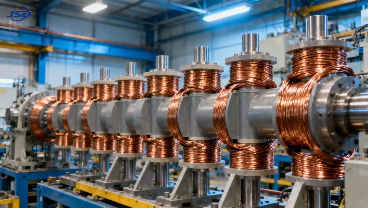
A copper winding alone does not establish adequate withstand capability. Winding geometry, conductor dimensions, insulation support, clamping, drying, and assembly tolerances all affect the result. Ask how the manufacturer controls winding preload and maintains support after insulation drying and settling. These questions reveal more than a general statement about material quality.
IEC 60076-5 addresses transformer ability to withstand short circuit. Where an IEEE specification applies, agree the relevant requirements and verification route explicitly. The purchase specification should identify the applicable standard and edition, acceptance criteria, and required evidence rather than listing “IEC/IEEE” without a defined basis.
Evidence may include a short-circuit test on the proposed design, an appropriately supported comparison with a tested reference design, and design calculations as permitted by the agreed requirements. These routes are not automatically equivalent. A report from another transformer is useful only when the supplier explains why its winding arrangement, dimensions, materials, impedance, and mechanical stresses are relevant to the offered unit.
Routine factory tests do not reproduce full short-circuit mechanical duty. A satisfactory ratio, resistance, loss, or dielectric test report therefore cannot replace the required withstand assessment.
Read the report, not just the certificate cover
Request the complete relevant report, including tested-unit identification, test conditions, measured currents, duration, and acceptance findings. Check how post-test condition was assessed under the applicable procedure. If the manufacturer offers a reference-design justification, require a comparison that identifies differences and explains their engineering significance.
ISO 9001 certification concerns the quality management system; it is not proof that a particular transformer can withstand the specified fault. Likewise, conformity markings and laboratory names should be checked for scope, model applicability, and supporting documentation. A long certification list is not a technical acceptance package.
Coordinate protection with the transformer’s limits
A capable manufacturer should provide usable data for protection coordination, not simply recommend a breaker size. The assessment must account for transformer inrush, permissible loading, through-fault withstand, and primary and backup clearing times. Where available and applicable, request damage or withstand curves and clarify their assumptions.
Check both ends of the fault range. Maximum current drives mechanical duty and equipment interrupting requirements. Minimum current can expose slow or insensitive protection, particularly for earth faults depending on the winding connection and grounding method. Selective coordination must not leave the transformer carrying a damaging fault for too long.
Do not treat a switchgear short-time rating as the transformer’s withstand rating. The components operate together, but their ratings and verification methods differ. The coordination study must show that the complete protection sequence remains within each component’s limits, including credible backup operation.
Use product specifications as a starting point
For a 10 kV distribution project, Jinshida Electric’s 10kV/0.4kV Oil-Immersed Power Distribution Transformer provides a candidate range for initial evaluation. Its published S-M series information covers 30–2,500 kVA, copper windings, 50 Hz or 60 Hz configurations, Dyn11 or Yyn0 options, and an optional FR3 vegetable insulating fluid. These parameters help establish application fit for industrial plants, urban distribution, renewable energy facilities, and public infrastructure.
They do not, by themselves, establish suitability for a high-fault-level installation. The selected configuration still needs guaranteed impedance, short-circuit duty confirmation, protection interfaces, and project-specific documentation. Frequency and vector-group options should be confirmed for the ordered unit rather than assumed to apply interchangeably.
The published short-term overload allowance—150% of rated capacity for no more than two hours, with oil temperature monitored at no more than 95 °C—also needs operating boundaries. Initial loading, ambient conditions, cooling, winding hot-spot temperature, and insulation ageing affect whether that allowance is appropriate. Overload capability is not evidence of short-circuit withstand.
Similarly, an efficiency claim exceeding 99% should be tied to the rating and measurement conditions. Compare guaranteed no-load and load losses, and verify applicable market efficiency requirements separately. If FR3 fluid is selected, confirm thermal design, material compatibility, site fire requirements, and maintenance procedures for that configuration.
Factory controls determine whether the delivered unit matches the design
The strongest design assessment loses value if production substitutions or uncontrolled assembly changes alter the winding support system. Review conductor and insulation traceability, dimensional inspections, drying records, clamping procedures, and controls for changes to critical materials or geometry. The supplier should explain which changes require renewed engineering review.
Jinshida Electric Power Technology Co., Ltd. describes its business as combining power equipment R&D, manufacturing, and application support, backed by a technical team and quality management processes. For an evaluator, the practical test of those capabilities is whether the team can connect the network study to the offered design, provide traceable records, and resolve technical deviations before production.
Agree an inspection and test plan early. Depending on project criticality, it may include witness points for specified tests, review of active-part inspection records, confirmation of accessories, and release documentation. For critical installations, consider whether baseline diagnostic measurements would support later transport checks or post-fault investigation.
Delivery readiness also includes transport arrangements, storage limits, installation instructions, and commissioning support. A low-maintenance or sealed construction does not eliminate inspection of bushings, connections, leaks, protective devices, or operating temperatures.
Make the award depend on evidence, not unresolved promises
Before comparing commercial offers, establish a technical acceptance threshold. Each shortlisted electrical power transformer manufacturer should provide:
- Confirmed fault-duty assumptions and guaranteed impedance with tolerances.
- An accepted short-circuit withstand verification route for the offered design.
- Data sufficient to complete protection coordination and grounding checks.
- A project-specific test plan, document schedule, and list of deviations.
- Defined responsibilities for commissioning, warranty assessment, and post-fault support.
Price and delivery time remain important, but compare them after technical gaps are visible. A lower-priced offer with unresolved withstand evidence may transfer engineering risk to the purchaser. The next useful step is a joint review of the single-line diagram, fault study, protection settings, and proposed transformer data sheet—with every remaining assumption assigned an owner and a closure date.

Get a Quote
Regardless of whether you require general advice or specific support, we are happy to help you.
Send Us Your Inquiry Today

Jinshida Electric remains committed to contributing to global energy development through professional manufacturing and superior service.