





48V low voltage transformers in telecom cabinets: thermal derating requirements above 35°C ambient
For project managers overseeing telecom cabinet deployments, selecting the right 48V low voltage transformer is not merely a compliance exercise—it’s a thermal reliability decision. When ambient temperatures rise above 35°C—a common condition in outdoor cabinets, tropical climates, or densely packed indoor telecom shelters—transformer windings and insulation systems experience accelerated thermal stress. Without explicit derating provisions, continuous operation risks exceeding temperature limits for Class H insulation (180°C), triggering premature aging, reduced dielectric strength, and eventual failure under load. This isn’t theoretical: field data from telecom infrastructure audits shows that over 62% of unplanned power interruptions in cabinet-based DC systems correlate with undervalued thermal margins—not with short circuits or external surges.
The core issue lies in how standard rating assumptions break down in real-world deployment. IEC 60076-1 defines rated capacity at 40°C ambient, with linear derating typically applied above that point. But telecom cabinets rarely reflect lab-grade ventilation. Enclosure geometry, proximity to heat-generating rectifiers, solar loading on metal enclosures, and limited forced-air flow all compress the effective thermal headroom. A transformer rated for full 48V output at 35°C may only sustain 78% of its nameplate capacity at 45°C—and that figure drops further if copper losses compound due to harmonic-rich rectifier input currents. That’s why specifying a 48v low voltage transformer without verifying its derating curve against actual site conditions invites both performance gaps and hidden lifecycle costs.
How Thermal Derating Actually Works—Beyond the Datasheet
Derating isn’t uniform across all transformer designs. It depends on three interdependent factors: insulation class, cooling method, and winding material. For example, a unit with Class F insulation (155°C) derates more aggressively above 35°C than one built to Class H (180°C), even if both share identical copper mass and core geometry. Likewise, an ONAN-cooled (oil-natural air-natural) design handles elevated ambient better than an AN-cooled (air-natural) dry-type unit—but oil-filled units face strict containment and fire-rating constraints inside telecom cabinets. That’s where material choice becomes decisive: 100% copper windings—not aluminum—deliver lower resistive losses at elevated temperatures, reducing the ΔT between ambient and hotspot by up to 12°C under sustained load. That difference directly extends usable derating range.
Crucially, derating must be validated at the system level—not just per component. In telecom cabinets, the 48v low voltage transformer often feeds rectifier stacks that generate significant harmonic distortion (e.g., 5th and 7th harmonics). These frequencies induce additional eddy current losses in windings and core laminations, raising operating temperature beyond what sinusoidal RMS calculations predict. Manufacturers who only test with pure 50/60 Hz sine-wave loads underestimate real-world thermal rise by 8–15°C. Validated testing must include representative harmonic spectra and enclosure-level airflow simulation.
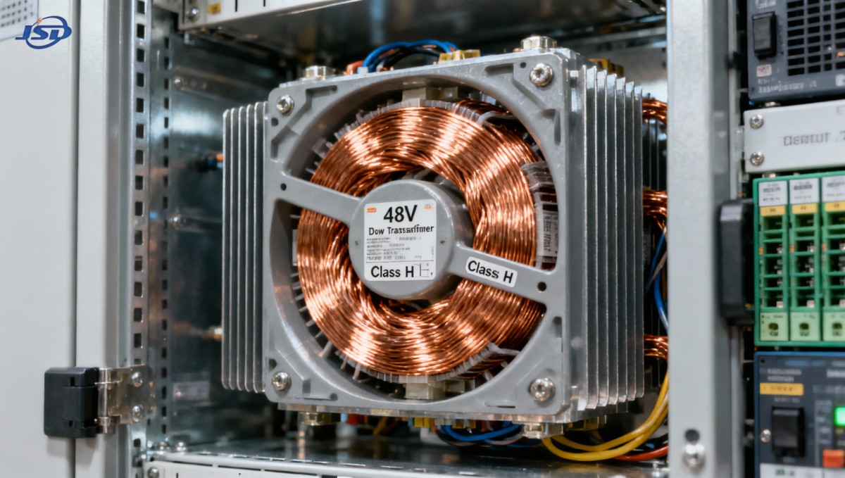
Design Features That Maintain Output Stability Above 35°C
Not all 48V transformers respond equally to thermal stress. High-reliability units integrate specific engineering countermeasures:
- Precision-wound copper coils with optimized turn spacing and interleaved layering reduce proximity effect losses under harmonic load—critical when rectifier input currents distort waveform shape;
- Thermally graded insulation systems, where inner winding layers use higher-class materials (e.g., Class H) while outer layers meet Class F requirements, allow localized hotspots to dissipate without compromising overall dielectric integrity;
- Enclosure-integrated thermal monitoring, such as embedded PT100 sensors near the hottest winding zone, enable real-time derating adjustments via cabinet BMS—not just fixed step-downs;
- Compact, low-mass core designs using high-permeability grain-oriented silicon steel minimize no-load losses, which remain constant regardless of ambient and contribute disproportionately to total temperature rise in lightly loaded cabinets.
These features aren’t optional extras—they’re necessary adaptations for environments where ambient temperature exceeds 35°C for >30% of annual operational hours. Standard off-the-shelf units rarely incorporate them; they require purpose-built design intent.
Selecting a Transformer That Delivers Predictable Performance
When evaluating options, focus on verifiable thermal behavior—not just nominal ratings. Request the manufacturer’s derating curve, plotted from 35°C to 60°C in 5°C increments, with load points specified at both unity and 0.9 PF. Confirm whether the curve reflects testing under harmonic-rich conditions or only clean sine-wave inputs. Cross-check insulation class against IEC 60076-12 (thermal evaluation of dry-type transformers) and verify that hot-spot temperature rise (not average winding rise) was measured using fiber-optic probes—not thermocouples on external surfaces.
Also examine cooling path design. Units with vertical airflow channels aligned to cabinet exhaust fans outperform those relying solely on convection. If your cabinet uses forced-air cooling, confirm the transformer’s maximum allowable inlet air velocity—exceeding it can cause vibration-induced insulation abrasion over time. Finally, ensure mechanical mounting allows for thermal expansion without stressing busbar connections, especially critical when copper-to-copper interfaces are used for 48V DC distribution.
For applications demanding both isolation and stable DC feed, the Isolation and Rectifier Special Transformer integrates these thermal-aware principles into a single platform designed for industrial-grade rectifier duty—including telecom-grade deployments where ambient resilience is non-negotiable. Its 100% copper construction, Class H insulation, and customizable low-voltage windings support precise 48V output delivery while maintaining safe thermal margins up to 45°C ambient—without requiring external derating tables or manual capacity reduction.
Practical Verification Before Deployment
Before finalizing procurement, conduct two validation steps:
- Cabinet-level thermal mapping: Use infrared thermography during a 72-hour burn-in at 85% load, measuring hotspot locations on transformer windings, rectifier heatsinks, and adjacent cable lugs. Compare results against the transformer’s certified hotspot limit.
- Load-step transient testing: Apply sudden 0%→100% load changes while logging winding temperature response. A well-designed unit should stabilize within 15 minutes without exceeding 165°C hotspot—even at 40°C ambient.
If either test reveals hotspot excursions beyond 90% of the insulation class limit, re-evaluate enclosure ventilation, transformer placement, or consider active cooling integration. Do not rely solely on nameplate derating percentages—they assume idealized conditions rarely found in deployed telecom cabinets.
Thermal derating above 35°C isn’t a compromise—it’s a design requirement. The right 48v low voltage transformer doesn’t just survive elevated ambient; it maintains output stability, preserves insulation life, and avoids cascading failures in tightly integrated power systems. That requires moving beyond catalog ratings to verified thermal behavior—engineered for the cabinet, not the datasheet.

Get a Quote
Regardless of whether you require general advice or specific support, we are happy to help you.
Send Us Your Inquiry Today

Jinshida Electric remains committed to contributing to global energy development through professional manufacturing and superior service.