





Do european compact substation transformer dimensions comply with EN 61869-11 space constraints?
Do European Compact Substation Transformer Dimensions Comply with EN 61869-11 Space Constraints?
If you’re specifying equipment for a retrofit in Berlin, a new urban substation in Lisbon, or a modular energy hub near Rotterdam, one question keeps coming up—not in procurement checklists, but in site walk-throughs and 3D coordination meetings: Will this transformer physically fit—and still meet the letter of EN 61869-11?
EN 61869-11 doesn’t define “compact.” It defines functional safety boundaries: clearance distances for live parts, minimum creepage paths across insulating surfaces, thermal envelope margins for forced-air-cooled units, and spatial allowances for verification access—especially around bushings, terminals, and cooling ducts. What’s “compact” on paper may fail compliance when installed in a confined steel enclosure with adjacent switchgear, cable trays, and maintenance walkways.
That mismatch—between dimensional marketing claims and real-world spatial compliance—is where project timelines stall. Not because of performance, but because of geometry: a 50 mm overhang at the HV terminal side can violate Clause 7.3.2 (access for dielectric testing), or a 120 mm rear clearance shortfall may breach Annex B’s thermal dissipation zone requirements under continuous 120% loading.
It’s not about footprint alone—it’s about functional envelope integrity
Many manufacturers quote “compact dimensions” based on the transformer’s bare chassis—excluding mounting rails, seismic brackets, integrated temperature sensors, or even the minimum air gap required for IR thermography during commissioning. EN 61869-11 is explicit: compliance must be verified in situ, with all accessories fitted and airflow paths unobstructed.
Take bushing orientation. A unit designed for wall-mounted vertical entry may meet width specs—but if your site requires horizontal termination into a compact ring-main unit (RMU), the effective depth increases by 180–220 mm due to elbow connector offsets and torque-access zones. That’s rarely reflected in datasheets labeled “EN 61869-11 compliant.”
Similarly, forced-air cooling isn’t just about fan selection. Clause 7.4.1 mandates minimum free-air volume around inlet/outlet grilles—typically ≥300 mm unobstructed on each side. In tight urban kiosks, that often means rethinking enclosure layout entirely, not just trimming transformer height.
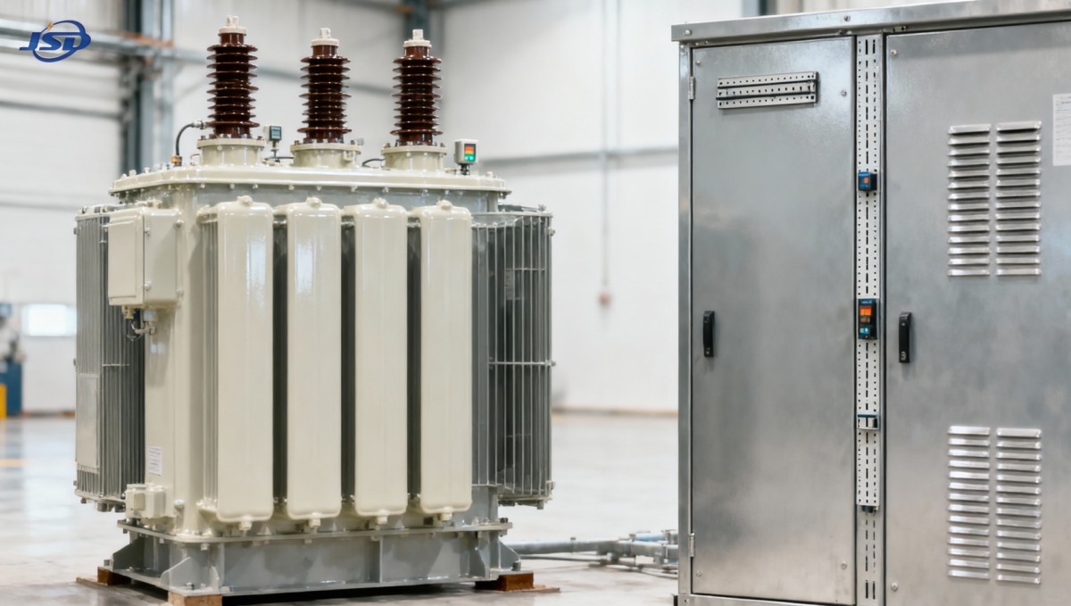
How Jinshida engineers for spatial reality—not just spec sheets
At Jinshida Electric Power Technology Co., Ltd., we treat EN 61869-11 not as a pass/fail checkbox, but as an integration protocol. Our R&D process starts with 3D spatial mapping—not just of the transformer core and coils, but of how it interfaces with common European RMUs, GIS feeders, and prefabricated substation cabins.
For example, our 11kV Three-Phase Cast Resin Dry-Type Distribution Transformer uses high-pressure copper strip winding and low-voltage copper foil technology—enabling tighter magnetic circuit control and reduced axial length without sacrificing short-circuit strength. The result? For a 1000 kVA unit, we achieve a depth reduction of ~115 mm versus conventional cast-resin designs—while maintaining full 95 kV lightning impulse withstand (per IEC 60076-3) and F1 fire rating.
That difference isn’t theoretical. It translates directly to whether the unit fits within the 1,450 mm depth limit of a standard Siemens Sivacon S8 substation cabinet—or avoids costly field modifications like recessed mounting plates or relocated busbar supports.
We also embed spatial awareness into certification. While CE and KEMA mark broad conformity, our internal validation includes physical mock-up testing against EN 61869-11 Annex D (verification of clearances under operational conditions) and third-party review of thermal airflow models—not just steady-state, but transient load cycling typical of EV charging hubs or solar-fed microgrids.
What to verify—before finalizing layout drawings
Don’t rely on “compliant” labels. Ask for:
- Clearance diagrams showing minimum distances from HV/LV terminals to enclosure walls—with all standard accessories installed (e.g., PT100 sensors, Buchholz simulators, grounding lugs)
- Airflow boundary files (STEP or IFC) confirming free-volume zones around fans and radiators—not just nominal fan dimensions
- Proof of Annex B thermal envelope validation: was it tested at 120% load with ambient +40°C, or only rated load at +20°C?
- Documentation of bushing torque-access radius—critical when space is shared with SF6 breaker actuators or cable management arms
And remember: EN 61869-11 references IEC 60076-11 for dry-type construction, but local grid codes (e.g., VDE-AR-N 4105 in Germany or ENTSO-E Technical Specifications) may impose stricter spatial or acoustic constraints. Always cross-check with your DSO’s technical connection guide—not just the standard.
When “compact” needs more than millimetres
True compactness isn’t just smaller—it’s smarter integration. That means designing for serviceability (e.g., top-accessible tap changers to avoid rear panel removal), thermal predictability (epoxy resin formulations with stable CTE across -25°C to +70°C cycles), and electromagnetic compatibility (low partial discharge design verified per IEC 60270—not just at factory test, but after transport vibration).
Jinshida’s approach reflects this: cold-rolled grain-oriented silicon steel cores with mineral oxide insulation reduce no-load losses below IEC 60076-1 limits, while patented flame-retardant epoxy systems allow thinner insulation layers—without compromising creepage distance. That’s how you gain 40–60 mm in coil diameter without sacrificing dielectric strength.
It also means supporting your engineering team—not just delivering a transformer, but sharing dimensional build packages, thermal simulation reports, and installation guidance tailored to modular cabin interfaces (e.g., ABB’s SafeRing or Schneider’s Premset).
Next steps: align specs with spatial truth
If your next European substation project is already in detailed design phase, don’t wait for clash detection to flag non-compliance. Request the full EN 61869-11 spatial verification dossier—not just a declaration of conformity. Confirm which clauses were validated physically (not just simulated), and ask for tolerance stack-up analysis across mounting, thermal expansion, and seismic anchoring.
And if you’re evaluating options for an 11 kV urban distribution network or industrial power supply system where space, fire safety, and long-term reliability are non-negotiable, consider how design choices cascade: lower losses mean less heat, which means smaller cooling envelopes; F1-class insulation eliminates oil containment, freeing up floor space; and vacuum-poured coils reduce risk of delamination in humid coastal sites—avoiding premature replacement cycles.
Because in modern grid infrastructure, the most valuable dimension isn’t height, width, or depth—it’s time saved on site.
Hot News
- 00
0000-00
How U.S. DOE efficiency rules affect distribution transformer manufacturers - 00
0000-00
How american type pad mounted transformer seismic qualification affects installation in California utility grids? - 00
0000-00
Do european compact substation transformer EMC compliance tests include conducted emissions up to 30MHz?
0000-00
Contact Us

Get a Quote
Regardless of whether you require general advice or specific support, we are happy to help you.
Send Us Your Inquiry Today

Jinshida Electric remains committed to contributing to global energy development through professional manufacturing and superior service.