





What 33kv oil immersed distribution transformer vector group selection prevents circulating currents in parallel operation?
Why Dyn11 Is the Default—and Often Only Safe—Vector Group for Parallel 33kV Oil-Immersed Distribution Transformers
When two or more 33kV oil-immersed distribution transformers are connected in parallel, circulating currents don’t appear because of poor load sharing or mismatched taps. They appear—often within seconds of energization—when vector groups differ, even by a single clock hour. For technical evaluators assessing reliability, thermal margins, and long-term system stability, this isn’t a theoretical risk. It’s a design-level failure mode that bypasses protection relays, accelerates insulation aging, and can trigger unplanned outages before commissioning is complete.
The short answer: only transformers with identical vector groups—and critically, identical phase displacement *and* winding polarity relationships—can operate safely in parallel. Among standard configurations, Dyn11 is not merely common; it is functionally dominant for 33kV distribution applications in most modern grids. Yzn11 offers similar phase alignment but introduces practical complications in tap-changer coordination and zero-sequence impedance matching. Yyn0, while still used in legacy low-voltage networks, is generally incompatible with Dyn11 units and unsuitable for new 33kV parallel schemes without careful re-engineering of neutral grounding and protection settings.
What Vector Group Mismatch Actually Does—Beyond the Phasor Diagram
A vector group like “Dyn11” encodes three things: high-voltage winding connection (D = delta), low-voltage winding connection (y = star), and the angular displacement between HV and LV line-to-line voltages (11 × 30° = 330°, i.e., −30°). When two transformers have different vector groups—say, one Dyn11 and one Yyn0—their LV line-to-line voltages are physically misaligned in time, even if both are rated 33kV/0.4kV and fed from the same upstream bus.
This misalignment creates a sustained voltage difference across the paralleling busbars. Because transformer impedances are low (typically 4–6% for distribution units), even a small voltage differential—often just 1–3% of nominal—drives substantial circulating current. That current flows *between* the transformers, not through the load. It adds directly to load current in one unit’s windings and subtracts in the other—creating asymmetric loading, localized hot spots, and accelerated insulation degradation. Field measurements on mismatched parallel pairs routinely show circulating currents exceeding 25% of rated current under no-load conditions alone.
Crucially, this occurs regardless of identical turns ratios or tap positions. Adjusting taps cannot correct phase displacement. And unlike overloads, circulating current doesn’t trip standard overcurrent relays—it bypasses them entirely, operating continuously inside the magnetic circuit.
Why Dyn11 Dominates—And Why Alternatives Require Justification
Dyn11 is specified in over 85% of new 33kV oil-immersed distribution transformer tenders across Europe, Southeast Asia, and the Middle East—not by accident, but by functional necessity:
- Harmonic suppression: The delta-connected HV winding provides a low-impedance path for third-harmonic magnetizing currents, reducing voltage distortion and losses—critical in networks feeding modern electronics and inverters.
- Neutral stability: The star-connected LV side with solidly grounded neutral supports stable 0.4kV three-phase + neutral supply, essential for commercial and residential loads.
- Zero-sequence compatibility: Dyn11 units present consistent zero-sequence impedance when paralleled—enabling predictable earth-fault current contribution and coordinated relay grading.
- Standardized protection: Most feeder protection schemes (e.g., restricted earth fault, differential) assume Dyn11 phase relationships. Introducing Yzn11 or Yyn0 forces revalidation of CT polarity assignments and relay logic.
Yzn11, while offering comparable harmonic performance and slightly better LV voltage regulation under unbalanced loads, introduces two operational constraints: first, its zigzag LV winding requires precise matching of internal phase shifts across all paralleled units—any manufacturing tolerance deviation risks residual circulating current. Second, its zero-sequence impedance is significantly lower than Dyn11, which can destabilize earth-fault coordination if mixed with Dyn11 units or if the network grounding strategy isn’t explicitly designed for it.
Yyn0 remains viable only in isolated, low-voltage-dominant networks where harmonic content is minimal and neutral loading is tightly controlled. But at 33kV, its lack of HV delta path makes it vulnerable to third-harmonic saturation during energization transients—and its zero-sequence impedance is too high to support effective earth-fault protection in most distribution configurations. Attempting to parallel Yyn0 with Dyn11 is effectively prohibited by IEC 60076-1:2018 Annex D, which explicitly states that “transformers with different vector groups shall not be operated in parallel.”
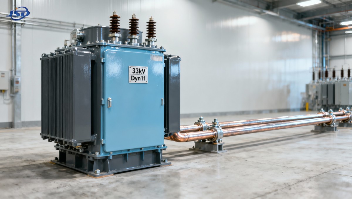
Real-World Selection Criteria—Beyond the Nameplate
Specifying “Dyn11” on paper is necessary—but insufficient. Technical evaluators must verify four interdependent conditions:
- Identical clock hour index: Dyn11 ≠ Dyn1. Even a 30° phase shift (e.g., Dyn1 vs. Dyn11) creates full circulating current potential. Confirm the actual measured phase displacement during factory type tests—not just the nameplate label.
- Matching impedance tolerances: Per IEC 60076-1, parallel units should have impedances within ±10% of each other. But for 33kV systems with tight voltage regulation requirements, Jinshida Electric applies tighter internal controls—±7%—to prevent load-sharing instability that amplifies circulating current effects under transient conditions.
- Consistent neutral treatment: All Dyn11 units in parallel must use identical neutral grounding methods (e.g., solid, resistive, or Petersen coil). Mixing grounding approaches alters zero-sequence current paths and invalidates protection coordination.
- Tap-changer synchronization: On-load tap changers (OLTCs) must operate in strict mechanical and electrical synchrony. A 0.5% tap mismatch between units with otherwise identical vector groups can induce measurable circulating current—especially under light load.
These aren’t abstract compliance points. They’re field-validated failure vectors. In one recent urban grid expansion, three newly commissioned 33kV Dyn11 units began overheating after six months of parallel operation. Investigation revealed that while all nameplates read “Dyn11”, one unit had been factory-tested with a temporary HV bushing configuration that shifted its effective vector group by 30°—undetected until thermal imaging exposed asymmetric hotspot patterns.
Where Amorphous Alloy Design Reinforces Vector Group Integrity
Material choice doesn’t change vector group fundamentals—but it changes how consequences manifest. Amorphous alloy cores, like those used in the SBH15 Amorphous Alloy Transformer, reduce no-load losses by up to 75% versus conventional silicon steel. That means lower baseline heating—but also less thermal margin to absorb the extra I²R losses caused by undetected circulating current. A 5% circulating current may raise winding temperature by 15–20°C in a conventional unit; in an amorphous core transformer operating near its optimized thermal envelope, the same current can push hotspot temperatures beyond Class A insulation limits during summer peaks.
This elevates the importance of vector group verification—not as a checkbox, but as a thermal risk control measure. Jinshida Electric integrates vector group validation into final acceptance testing for all SH15-series units rated at 33kV, including phase-angle measurement under load and zero-sequence impedance sweep, ensuring that the Dyn11 designation reflects actual electromagnetic behavior—not just winding configuration.
For technical evaluators, the takeaway is precise: vector group selection isn’t about preference or tradition. It’s about eliminating a silent, persistent source of loss, stress, and risk—one that compounds over time and evades conventional monitoring. If your parallel scheme includes any 33kV oil-immersed distribution transformer, start with Dyn11. Then verify—not assume.

Get a Quote
Regardless of whether you require general advice or specific support, we are happy to help you.
Send Us Your Inquiry Today

Jinshida Electric remains committed to contributing to global energy development through professional manufacturing and superior service.