





Do electrolysis rectifier transformer harmonic filters meet IEC 61000-3-6 requirements?
Do electrolysis rectifier transformer harmonic filters meet IEC 61000-3-6 requirements?
Short answer: Not automatically—and not by design alone. Harmonic filters integrated with electrolysis rectifier transformers can meet IEC 61000-3-6, but compliance is not inherent to the filter’s presence, nor guaranteed by transformer rating or manufacturer claims. It depends on three tightly coupled conditions: (1) system-level harmonic emission modeling that includes source impedance, background distortion, and load dynamics; (2) filter tuning precision verified under real operating harmonics—not just theoretical 5th/7th orders; and (3) third-party validation against the full methodology of IEC 61000-3-6, including aggregation rules for multiple installations and contribution limits at the point of common coupling (PCC).
For quality control and safety managers responsible for aluminum smelters, chlorine plants, or other electrochemical facilities, this distinction is operational, not academic. A non-compliant filter doesn’t just risk regulatory rejection—it can accelerate insulation aging in adjacent equipment, trigger relay misoperations during transient loading, and contribute to voltage distortion that destabilizes sensitive process controls. Worse, many “harmonic mitigation” packages are certified only to IEC 61000-3-2 (for equipment emissions) or IEC 61000-4-7 (measurement methods), which do not address the grid-impact assessment required by IEC 61000-3-6.
Why IEC 61000-3-6 is non-negotiable in electrolysis applications
Electrolysis rectifier transformers feed large-scale 6-pulse or 12-pulse thyristor-controlled rectifiers—systems that inject high-magnitude, low-order harmonics (especially 5th, 7th, 11th, 13th) directly into the supply network. Unlike general industrial loads, electrolysis cells operate continuously at near-full load for months, with minimal harmonic cancellation from variable demand. This creates sustained harmonic current injection that accumulates across feeders, substations, and shared PCCs.
IEC 61000-3-6 doesn’t set fixed harmonic current limits. Instead, it defines a shared responsibility framework: each customer must limit its harmonic contribution to levels that ensure the total distortion at the PCC stays within acceptable thresholds (e.g., 8% THDV for MV networks). The standard requires rigorous calculation of individual harmonic current emission limits based on short-circuit capacity at the PCC, existing background distortion, and the number of contributing users. A filter designed without this system context may suppress local harmonics—but still over-contribute relative to its allocated share.
This is where assumptions break down. Some suppliers specify filters tuned to 4.7th or 6.3rd order based on nominal rectifier pulse count—yet actual harmonic spectra shift under load unbalance, DC current ripple, and transformer saturation. Others validate only at rated load, ignoring the fact that electrolysis plants routinely operate between 70–110% of nominal DC current, altering harmonic magnitude and phase relationships. Without dynamic verification across the operational envelope, IEC 61000-3-6 compliance remains unproven.
What verification actually requires—and what’s often missing
True IEC 61000-3-6 alignment demands more than component-level testing. It requires:
- System modeling using validated software (e.g., EMTP-RV or DIgSILENT PowerFactory) with site-specific parameters: upstream network impedance, cable lengths, parallel feeders, and measured background harmonics over ≥7-day intervals;
- Filter performance testing under representative load profiles—not just steady-state, but including ramp-up, load shedding, and anode-changing transients—measuring harmonic current reduction at the PCC, not just at the transformer LV terminals;
- Third-party certification that explicitly references IEC 61000-3-6:2018 (or latest edition), including documentation of the aggregation method used, the assumed short-circuit ratio (SCR), and the justification for assigned emission limits;
- Traceable measurement per IEC 61000-4-30 Class A, with synchronized voltage and current capture at both the PCC and the rectifier transformer secondary—essential for separating plant-generated distortion from grid-originated distortion.
Many specifications omit the first and last items entirely. Filter datasheets commonly list “harmonic attenuation >90% @ 5th & 7th” —but without stating test conditions, reference impedance, or whether measurements were taken upstream or downstream of the filter. That number becomes meaningless when evaluating contribution limits under IEC 61000-3-6.
Where distribution-grade transformers fit—and where they don’t
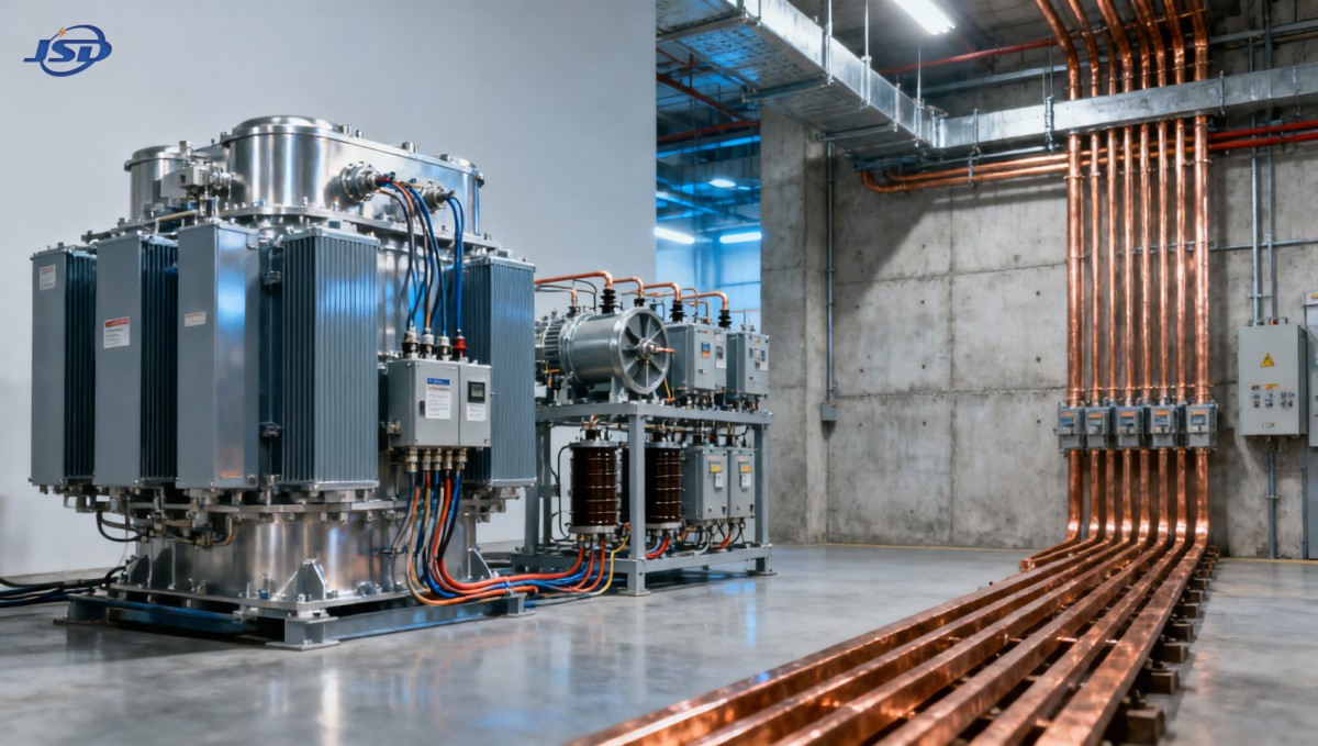
It’s important to distinguish roles: electrolysis rectifier transformers are specialized units built for high DC current, low impedance, and thermal resilience under severe harmonic flux. Distribution transformers—like the 10kV Cast Resin Dry-Type Distribution Transformer—serve different functions. They step down from 10 kV to 0.4 kV for auxiliary systems: cooling pumps, fume extraction, control power, and lighting. While these units must tolerate harmonic-rich environments (e.g., from VFDs feeding recirculation fans), they are not part of the primary harmonic emission path.
That said, their design impacts overall system resilience. For example, cast-resin units with F1-class fire performance and vacuum-poured windings offer superior resistance to thermal stress from stray harmonic losses—a practical advantage when installed near rectifier halls. Their low-loss core construction (using cold-rolled grain-oriented silicon steel) and copper foil LV windings also reduce additional harmonic heating—indirectly supporting stable operation of protection relays and metering systems that monitor PCC compliance. But no distribution transformer, however well-built, substitutes for a properly engineered and verified harmonic filter on the rectifier transformer itself.
Practical steps for quality and safety teams
Before accepting a harmonic mitigation solution, verify these four checkpoints:
- Request the full IEC 61000-3-6 compliance report—not just a certificate logo. It must include the PCC short-circuit capacity used, the background harmonic data source, the harmonic contribution allocation method (e.g., “equal sharing” vs. “capacity-based”), and measured harmonic current spectra at PCC before/after filter commissioning.
- Confirm filter tuning is field-adjustable. Fixed-tuned passive filters drift with temperature and aging. Electrolysis plants benefit from filters with tunable reactors or hybrid active-passive topologies that maintain resonance accuracy across ambient ranges of −25°C to +45°C.
- Require harmonic impact assessment for future expansion. If your facility plans to add a second potline or upgrade rectifier capacity, ask how the existing filter allocation will be re-evaluated under IEC 61000-3-6 Annex C—many reports assume static load, not scalable infrastructure.
- Validate measurement points. Ensure harmonic monitoring is installed at the utility-defined PCC—not just at your main incomer. Discrepancies between those locations have derailed multiple compliance audits.
Compliance isn’t a one-time checkbox. It’s a living condition—one that evolves with grid changes, equipment aging, and operational shifts. For electrolysis operators, treating IEC 61000-3-6 as a design prerequisite—not a post-installation audit item—is the only way to avoid unplanned shutdowns, utility penalties, or forced retrofits mid-production cycle.
Hot News
- 00
0000-00
How U.S. DOE efficiency rules affect distribution transformer manufacturers - 00
0000-00
How american type pad mounted transformer seismic qualification affects installation in California utility grids? - 00
0000-00
Do european compact substation transformer EMC compliance tests include conducted emissions up to 30MHz?
0000-00
Contact Us

Get a Quote
Regardless of whether you require general advice or specific support, we are happy to help you.
Send Us Your Inquiry Today

Jinshida Electric remains committed to contributing to global energy development through professional manufacturing and superior service.