





Why Three-Phase High-Voltage Transformers Improve Power Distribution
A three phase high voltage transformer improves power distribution because it moves large amounts of electrical power at a voltage level that keeps current manageable, then supplies a balanced three-phase output suited to utility networks and heavy industrial loads. Lower current for the same power transfer reduces conductor heating and voltage drop, allowing feeders, switchgear, and cables to operate more efficiently over distance.
The benefit is not simply that the transformer changes voltage. Its winding arrangement, phase relationship, impedance, cooling design, and connection to the surrounding network determine whether the delivered power remains stable when loads change. In a distribution system serving motors, substations, converters, pumps, furnaces, or rail equipment, those details affect voltage quality, fault behavior, energy losses, and maintenance demands.
Higher voltage reduces current-related losses
For a given amount of three-phase power, raising the transmission voltage lowers the current required in each conductor. This matters because conductor losses increase with the square of current. A feeder carrying excessive current generates heat in cables, busbars, terminals, and switch contacts. That heat represents lost energy and can accelerate insulation aging.
A high-voltage transformer makes it practical to transfer power through a medium- or high-voltage section of the network before stepping it down near the point of use. The shorter low-voltage section then carries the higher current only where it is needed. This arrangement is especially useful where a large load is separated from the incoming supply by long cable routes, overhead lines, or extensive plant distribution runs.
Voltage alone does not guarantee low losses. Transformer load losses also rise with current, while core losses occur whenever the transformer is energized. A unit selected only for a high voltage rating but operated far below or above its intended loading range can waste energy for different reasons. The useful comparison is the total system loss at the expected load profile, including conductors and associated equipment, rather than a transformer nameplate value viewed in isolation.
Three phases carry heavy loads with a balanced electrical pattern
Three-phase power uses three sinusoidal voltages separated by 120 electrical degrees. When loads are reasonably balanced, power transfer is smoother than in a single-phase arrangement, and rotating machines develop a naturally rotating magnetic field. This is why three-phase systems are common wherever substantial motors, compressors, conveyors, crushers, pumps, and process equipment are involved.
A three phase high voltage transformer preserves or intentionally changes the phase relationships needed by the downstream system. Balanced loading limits neutral current, reduces voltage unbalance, and supports predictable motor performance. A motor operating with materially unequal phase voltages may draw uneven phase currents, run hotter, and deliver less reliable torque even when the average voltage appears acceptable.
Load balance should be assessed at the transformer terminals and over time. A system can look balanced during a brief inspection yet experience recurring imbalance when large single-phase loads cycle on and off. The result may be one phase approaching its thermal limit while the overall kVA demand still appears within the transformer rating. This is one reason why phase-current records and load profiles are more informative than a single total-load reading.
Voltage regulation keeps equipment operating within a usable range
Distribution voltage changes as current flows through transformer windings and feeder impedance. A transformer with suitable impedance and tap settings helps keep the secondary voltage close to the intended operating range as load changes. This is important because loads react differently to voltage variation. Induction motors may draw more current when voltage falls under a demanding mechanical load; electronic drives and rectifiers can create a different current response; resistance heating equipment changes output as voltage changes.
Tap selection is frequently misunderstood. A tap position does not create unlimited voltage correction. It establishes a ratio appropriate for the expected primary supply condition and target secondary voltage. If the upstream voltage varies widely, a fixed tap cannot make every operating point ideal. Conversely, changing taps without confirming the actual high-voltage supply, secondary voltage, connection group, and load condition can move the problem from one part of the operating range to another.
Transformer impedance also deserves context. Higher impedance can limit fault current and reduce mechanical stress during short circuits, but it also produces more voltage drop under load. Lower impedance can improve regulation, yet may increase available fault duty for downstream breakers and busbars. The appropriate value is a network coordination decision, not a universal preference for the lowest possible number.
Isolation and winding connections improve network behavior
Electrical isolation separates circuits while transferring energy magnetically. It limits direct conductive paths between primary and secondary systems and supports grounding arrangements appropriate to the installation. Isolation is particularly relevant where sensitive control equipment, power electronics, or rectifier loads share a supply with other equipment.
The selected vector group influences phase displacement, neutral availability, and the path taken by certain harmonic currents. For example, a delta winding can provide a closed path for triplen harmonic currents and can help prevent those components from appearing in the upstream line currents in the same way they would in a different connection. A wye secondary may be selected when a neutral point is required. These are system-level choices: a connection that is suitable for one grounding and load arrangement may complicate parallel operation with an existing transformer that has a different phase displacement.
Parallel transformers require more than similar power ratings. Their voltage ratios, tap positions, vector groups, percent impedance, and impedance angles must be compatible enough to share load properly. If these values differ substantially, circulating current can flow between transformers or one unit can become overloaded before the other reaches its rating. Adding capacity without reviewing these relationships can therefore create a distribution problem instead of resolving one.
Large nonlinear loads require a different interpretation of capacity
Industrial rectifiers, variable-speed drives, arc processes, electrolysis equipment, and some rail traction systems draw current that is not a clean sine wave. Harmonic current increases heating in windings, conductors, and associated equipment. It can also distort voltage when network impedance is significant. A transformer that performs acceptably on a conventional motor load may require a modified thermal design for a rectifier duty with pronounced harmonic content.
For this type of service, secondary voltage, phase shift, pulse arrangement, harmonic spectrum, overload cycle, and cooling method should be evaluated together. Stating only the kVA rating leaves major questions unanswered. A rectifier load may have short high-current intervals, a near-continuous base load, or both. Heat accumulation depends on the duration and repetition of those intervals, not merely on the highest recorded current.
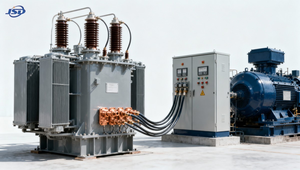
Where a distribution stage must feed rectification equipment while maintaining galvanic isolation, an Isolation and Rectifier Special Transformer illustrates the type of application-specific arrangement involved. Units in this category may use three-phase high-voltage inputs such as 6 kV, 10 kV, 20 kV, or 35 kV, with a secondary voltage tailored to the rectifier system. Copper windings, suitable connection groups, and either oil-natural or air-natural cooling are selected in relation to the electrical duty and site conditions rather than as interchangeable features.
Reliability comes from thermal margin and mechanical integrity
Power distribution reliability is often discussed as an electrical issue, but transformer condition is strongly affected by heat, moisture, contamination, and mechanical forces. Insulation life is influenced by operating temperature and repeated thermal cycling. Loose connections or inadequate contact pressure can create localized hot spots that are not visible from the transformer rating alone.
Copper conductors offer good conductivity and support compact winding designs, but conductor material is only one part of thermal performance. The winding geometry, insulation system, core construction, oil circulation or air path, radiator clearance, ambient temperature, and load pattern all influence temperature rise. An indoor dry-type installation with restricted ventilation faces a different cooling problem from an outdoor oil-filled unit exposed to high ambient temperatures and direct solar gain.
Short-circuit strength also matters. During a fault, windings experience strong electromagnetic forces before protective devices clear the current. The transformer must have conductors, clamping, insulation supports, and lead arrangements able to withstand the expected duty. A transformer can show normal no-load test results yet have reduced reliability if repeated fault events have displaced windings or weakened connections.
Installation details can preserve or undermine the expected benefit
The distribution improvement promised by a three-phase high-voltage transformer depends on the complete installation. Cable terminations must match the conductor size, insulation class, and connection geometry. Inadequate bend radius, unsupported cable weight, poor stress control, or incorrect torque can introduce heating and partial-discharge risks at interfaces that are often mistaken for transformer faults.
Grounding should be designed around the winding connection and protection philosophy. Treating every neutral point as though it has the same function can lead to misleading fault-current expectations. Surge protection, cable shielding, and the location of the transformer relative to switching equipment also affect transient stresses. Long cable runs feeding power electronic loads deserve particular attention because reflected-wave effects and switching transients may stress insulation differently from a short conventional feeder.
Transport and placement are relevant as well. Shock during delivery, inadequate lifting points, or prolonged storage in damp conditions can affect a transformer before commissioning. After installation, phase sequence, ratio, insulation resistance, protective settings, terminal tightness, and cooling clearances should be verified against the actual design documents. These tasks are not administrative formalities; they establish whether the installed equipment matches the assumptions used for system coordination.
Reading specifications without common shortcuts
A common error is treating the rated capacity as a direct statement of usable output under every condition. The rating is meaningful only with its specified cooling and temperature assumptions. Another error is assuming that customized secondary voltage is merely a convenience. In converter and rectifier systems, the secondary voltage affects the resulting DC output and operating margin, so a small ratio error can carry through the rest of the process.
Monitoring reveals whether distribution performance is holding
Routine observation should focus on changes, not only absolute readings. A gradual difference between phase currents, rising top-oil or winding temperature at a familiar load, increased fan runtime on an air-cooled design, unusual sound, oil leakage, discolored terminals, or recurring protection alarms can point to a developing condition. The cause may lie in the transformer, but it can also originate in a deteriorated cable joint, shifted process load, failed cooling path, or altered upstream voltage.
Testing and inspection results are most useful when compared with commissioning values and prior records. A single insulation reading without temperature context, for example, is less revealing than a trend taken under comparable conditions. The same applies to dissolved-gas analysis for oil-filled transformers, thermal imaging of connections, and harmonic measurements on nonlinear loads. Each technique answers a different question; none substitutes for understanding the load and network arrangement.
By reducing transmission current, maintaining three-phase balance, supporting voltage regulation, and separating circuits where required, a properly matched high-voltage transformer strengthens the distribution path between the source and the load. Its real value appears when electrical ratings, connection details, thermal conditions, and installation constraints are treated as one operating system.

Get a Quote
Regardless of whether you require general advice or specific support, we are happy to help you.
Send Us Your Inquiry Today

Jinshida Electric remains committed to contributing to global energy development through professional manufacturing and superior service.