





Three-Phase High-Voltage Transformer Sizing for Large Motor Loads
Sizing a three phase high voltage transformer for large motor loads requires more than matching nameplate kVA. Technical evaluators must account for motor starting current, load profiles, voltage regulation, harmonic effects, insulation requirements, and future capacity expansion.
The correct selection balances initial capital cost against process reliability, motor life, power quality, and operating flexibility. A transformer that appears adequate under steady-state conditions can still cause nuisance trips, excessive voltage dip, or failed motor acceleration.
Start With the Actual Motor Duty, Not Only Installed kW
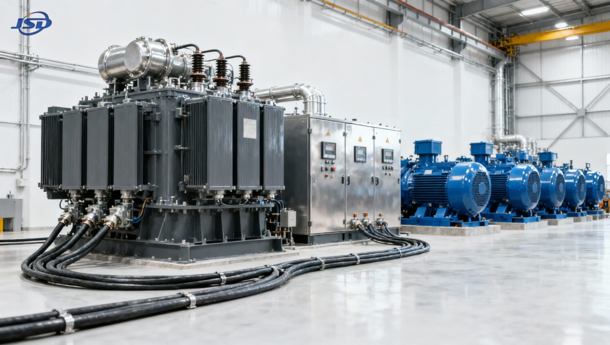
The first sizing step is to define the electrical duty of every motor connected to the transformer. Installed motor power is useful, but it does not describe simultaneous operation, starting sequence, loading level, or acceleration demand.
For a three phase high voltage transformer, the continuous load calculation should include each motor's rated output, efficiency, power factor, and expected mechanical loading. Motors driving lightly loaded equipment may consume substantially less than their nameplate input.
Convert motor output power into electrical input demand before building the load schedule. For a motor rated in kilowatts, divide shaft output by expected efficiency, then divide again by operating power factor to estimate apparent power.
For example, a 500 kW motor operating at 95% efficiency and 0.88 power factor requires approximately 598 kVA at full load. This value is the starting point for continuous transformer loading, not the motor's 500 kW rating.
Technical evaluations should classify loads by operating pattern: continuously running motors, intermittent motors, standby drives, cyclic loads, and motors that can start concurrently. This classification prevents unnecessary oversizing while protecting critical operating scenarios.
Process equipment often has different maximum-demand and maximum-starting-demand conditions. A pumping station may run several pumps together but start them sequentially. A crushing line may impose peak torque and high current during loaded starts.
Include non-motor loads on the same bus, such as lighting, heaters, rectifiers, control power, variable-frequency drives, capacitor banks, and auxiliary transformers. Their demand may be small individually but material in a tightly sized installation.
A documented load list should state rated kW, full-load current, starting method, duty cycle, voltage, power factor, efficiency, criticality, and simultaneous-operation factor. This document is more valuable than a simple connected-load total.
Calculate Continuous kVA and Apply a Practical Loading Margin
After establishing operating demand, calculate the required continuous transformer capacity in kVA. For balanced three-phase loads, apparent power can be estimated from line voltage and current using kVA equals root three multiplied by volts and amps divided by 1,000.
Alternatively, sum the estimated kVA of the individual loads expected to run at the same time. This method is usually clearer for engineering reviews because it preserves the assumptions behind diversity, process loading, and future additions.
Do not assume that a transformer should routinely operate at its nominal rating. Ambient temperature, enclosure design, altitude, harmonic loading, cooling condition, and expected service life all affect the appropriate continuous operating level.
For many industrial projects, a preliminary target of 70% to 85% normal transformer loading provides useful operational flexibility. The final value should reflect the transformer cooling class, site conditions, maintenance philosophy, and verified load forecast.
Margin is especially important where production expansion is likely. Selecting a transformer with no reserve may reduce purchase cost today, yet create major outage, civil-work, and switchgear replacement costs when one additional motor is installed.
However, excessive oversizing also has consequences. A significantly oversized unit can increase no-load losses, purchase cost, footprint, and short-circuit duty. It may also operate less efficiently during prolonged low-load periods.
Evaluate loss performance at the expected load profile, not only at rated capacity. Core losses occur whenever the transformer is energized, while winding losses rise approximately with the square of load current.
The best capacity is therefore not automatically the largest available rating. It is the rating that carries verified continuous demand efficiently, maintains voltage during credible motor starts, and preserves an economically justified expansion allowance.
Motor Starting Current Usually Governs the Final Selection
Large induction motors can draw several times full-load current during starting. If transformer impedance and upstream system impedance are not evaluated, the resulting voltage dip can prevent the motor from reaching speed or disturb other connected equipment.
Across-the-line starting commonly produces inrush current of approximately six to eight times rated current. Actual values depend on motor design, voltage, load inertia, rotor characteristics, and the condition of the driven machine.
Starting kVA is not simply a transformer capacity requirement that must be supplied continuously. Instead, it is a short-duration system event requiring enough source strength to maintain acceptable voltage at the motor terminals.
Voltage dip should be calculated from transformer impedance, available upstream short-circuit capacity, feeder impedance, and the motor's starting current. Long medium-voltage cables, weak utility connections, and high-impedance transformers can compound the problem.
The acceptable dip depends on the motor, starting equipment, process, and other loads. Many systems target a motor-terminal voltage that preserves adequate starting torque while avoiding control resets, contactor dropout, or disruption to sensitive electronics.
Acceleration torque falls sharply as voltage declines. For induction motors, available torque is approximately proportional to the square of terminal voltage. A modest voltage reduction can therefore make a high-inertia or loaded start unsuccessful.
Review the worst credible start, not merely the largest motor. The most demanding scenario may involve a medium-sized motor starting under load while other major motors are running and the utility supply is at its lower voltage limit.
Where direct-on-line starting creates an unacceptable dip, alternatives include soft starters, autotransformer starters, reactor starters, variable-frequency drives, staggered-start logic, or a lower-impedance transformer configuration. Each option should be compared at system level.
Use Transformer Impedance as a Design Variable
Transformer impedance is central to motor-starting performance and short-circuit coordination. Lower impedance generally reduces voltage drop during a large motor start, but it also increases available fault current at the secondary bus.
Higher impedance can limit downstream fault duty and may simplify switchgear ratings. Yet it can produce excessive voltage depression when a large motor starts, particularly where the transformer serves a compact bus with several process-critical loads.
Technical evaluators should request the transformer impedance tolerance, not only the nominal percentage impedance. Manufacturing tolerances, tap position, source strength, and cable impedance should be represented in the design calculation.
For parallel transformers, impedance matching becomes even more important. Units with materially different voltage ratios or impedances may not share load properly, creating circulating currents and uneven thermal loading.
Transformer impedance must also be coordinated with protection settings. The selected design should support selective operation of relays, fuses, breakers, and motor protection devices without exceeding the interrupting ratings of installed equipment.
A robust design review includes a short-circuit study and a motor-starting study using the intended one-line diagram. Spreadsheet estimates can screen options, but major facilities should validate the selected arrangement with recognized power-system analysis software.
Specify the actual operating tap range and nominal primary voltage. A transformer that performs well at nominal supply may deliver insufficient motor terminal voltage when the incoming grid operates at the lower end of its permitted range.
For critical operations, assess both normal and contingency source conditions. A temporary generator supply, a single-transformer contingency, or a reduced utility fault level can materially change starting performance and protection behavior.
Choose Winding Connections and Voltage Taps for the Application
Winding configuration affects grounding, fault behavior, harmonic circulation, and the availability of a neutral. Common arrangements include delta-wye, wye-delta, delta-delta, and grounded-wye to grounded-wye configurations with appropriate system grounding treatment.
A delta primary can help isolate certain zero-sequence conditions and provide a path for triplen harmonic currents. A grounded-wye secondary often supports low-voltage distribution where line-to-neutral auxiliary loads and a stable reference are required.
The required vector group should be confirmed with the facility's protection, metering, and parallel-operation requirements. Phase displacement can affect synchronization, relay polarities, power quality equipment, and the ability to connect transformers in parallel.
Off-circuit taps or on-load tap changers may be appropriate where primary voltage varies significantly. Their purpose is to keep secondary voltage within a practical operating range, especially where motor torque and drive performance are sensitive.
Tap selection should account for expected source voltage, feeder voltage drop, and the desired no-load secondary voltage. A nominally correct ratio can still be unsuitable if the final motor bus voltage is too low under normal operation.
For outdoor installations, specify insulation level and clearances according to system voltage, lightning exposure, pollution severity, and applicable standards. High-voltage transformer selection must include more than the low-voltage kVA calculation.
Insulation coordination should address BIL, surge arresters, cable terminations, switchgear insulation class, and grounding. These details influence long-term reliability and must align across the complete medium-voltage distribution system.
Site altitude and ambient temperature also matter. Reduced air density affects cooling and insulation performance, while high ambient temperatures can require derating or a transformer designed with additional thermal margin.
Account for Drives, Harmonics, and Nonlinear Load Effects
Modern large motor systems increasingly use variable-frequency drives to improve process control and reduce mechanical stress. These drives can lower starting current, but they introduce harmonic currents that must be considered in transformer design.
Harmonics increase winding eddy-current losses and can raise transformer hot-spot temperature beyond expectations based on fundamental current alone. A standard transformer may require derating when serving substantial nonlinear load.
Request harmonic data from drive suppliers, including expected current distortion, pulse configuration, filter arrangement, and operating range. The assessment should consider both individual drive behavior and aggregate effects across the common bus.
Where harmonic loading is material, specify a transformer suitable for the calculated harmonic spectrum, potentially with enhanced winding design, electrostatic shielding, adjusted impedance, or an appropriate K-factor approach where applicable.
Capacitor banks require separate attention. Capacitors can improve power factor but may create resonance with transformer and system inductance, amplifying harmonic currents. Detuned reactors or harmonic filters may be necessary.
Voltage-source drives can also create fast switching transients at motor terminals. Although this is primarily a motor-cable-drive coordination issue, transformer selection should be integrated with the complete power quality and grounding strategy.
For mixed loads, separate transformers may be justified when large direct-on-line motors, sensitive controls, and high-harmonic drive loads would otherwise interfere. The cost of separation can be lower than repeated production disturbances.
Power quality requirements should be written into the technical specification. Define acceptable voltage distortion, voltage unbalance, flicker limits, and transient performance at the relevant bus rather than relying on generic transformer descriptions.
Consider Energy Storage When Motor Starts Affect the Facility Bus
In facilities with constrained utility capacity, recurring peak demand, or sensitive processes, energy storage can complement transformer sizing. It does not replace correct transformer engineering, but it can reduce stress during managed peak and contingency conditions.
A battery energy storage system can support a low-voltage bus during selected high-demand intervals, depending on its inverter capability, protection scheme, control response, and grid-interconnection design. Its role must be defined through system studies.
For commercial and industrial applications, the 500kW/1MWh Air Cooling Container Energy Storage System provides 500 kW PCS capacity and 1 MWh LiFePO4 storage in a standard 20-foot outdoor container.
Its three-phase, four-wire 400 V AC output makes it relevant on compatible low-voltage distribution systems. It can support peak shaving, photovoltaic integration, backup strategies, and microgrid operation when coordinated with the facility transformer and switchgear.
Technical evaluators should distinguish between energy capacity and power capacity. A 1 MWh battery may have substantial stored energy, but its ability to assist a motor event depends on inverter kW output, overload capability, and response duration.
Storage controls must avoid unintended islanding, protection conflicts, or circulating power. A successful solution requires coordinated settings among the EMS, BMS, PCS, transformer protection, generator controls, and utility interconnection equipment.
In some projects, storage enables a smaller grid import profile without reducing process output. In others, the transformer must still be sized for full motor demand because storage availability cannot be treated as guaranteed under every operating condition.
Evaluate the business case using actual demand charges, outage costs, renewable generation profile, start frequency, and required resilience. A technically capable storage system should be selected only after the transformer and motor-load studies establish its value.
Specify Thermal Performance, Construction, and Reliability Requirements
Transformer type selection typically involves dry-type and liquid-filled designs. The appropriate choice depends on installation location, fire requirements, environmental conditions, available space, efficiency targets, maintenance capability, and local regulatory requirements.
Liquid-filled transformers can offer high efficiency and compact capacity for demanding outdoor applications. Dry-type transformers may be preferred indoors or where fire-risk policies, building constraints, or environmental considerations favor reduced liquid containment requirements.
Specify the cooling class, temperature-rise limit, insulation system, winding conductor material, enclosure rating, and required accessories. These details determine whether the delivered transformer matches the calculated thermal and environmental duty.
Common accessories include temperature sensors, winding temperature indicators, pressure relief devices, oil level indicators, Buchholz relays where applicable, surge arresters, monitoring terminals, and remote alarm contacts for supervisory systems.
For outdoor equipment, enclosure corrosion resistance should match the site atmosphere. Coastal, chemical, mining, and high-humidity environments may require enhanced coatings, stainless hardware, sealed interfaces, or more frequent inspection procedures.
Reliability also depends on transport, installation, and commissioning quality. Confirm lifting arrangements, foundation loads, cable termination space, earthing points, oil handling requirements, and access for testing and routine maintenance before procurement.
Factory acceptance testing should verify ratio, winding resistance, insulation resistance, impedance, dielectric performance, and functional operation of specified accessories. Additional tests may be justified for critical projects or unusual service conditions.
Jinshida Electric Power Technology Co., Ltd. supports power transmission and distribution applications with an engineering-led approach to product quality, manufacturing control, and reliable power equipment selection for industrial and infrastructure projects.
Use a Decision Checklist Before Releasing the Purchase Order
A defensible transformer selection should be supported by a complete single-line diagram, verified load schedule, motor-starting study, short-circuit study, protection coordination review, harmonic assessment, and environmental design basis.
Confirm the primary voltage range, secondary voltage, frequency, vector group, rated kVA, impedance, tap arrangement, insulation level, cooling method, and grounding configuration. These items should be stated clearly in the technical specification.
Review the largest motor start at minimum source voltage and maximum coincident running load. Also test realistic abnormal scenarios, including loss of one parallel transformer, emergency operation, and starting after a process shutdown.
Check secondary switchgear short-circuit ratings against calculated fault duty. A low-impedance transformer selected to improve motor starts may require higher-rated breakers, busbars, cables, current transformers, and protection devices.
Request guaranteed loss data and evaluate lifecycle cost where operating hours are high. Comparing no-load and load losses at the expected load profile provides a more meaningful result than comparing purchase prices alone.
Ensure that future capacity is based on a documented expansion plan. Reserve margin should represent credible new motors, production lines, or electrification initiatives rather than an arbitrary percentage added without operational justification.
Finally, define acceptance criteria for voltage regulation, starting performance, temperature rise, sound level, protection interfaces, documentation, testing, warranty, and commissioning support. Clear criteria reduce ambiguity between engineering, procurement, and suppliers.
For large motor installations, the right transformer is a system decision. Selecting capacity, impedance, voltage control, insulation, and power-quality features together produces stable acceleration, lower operational risk, and a more durable investment.
Conclusion
A three phase high voltage transformer should be sized from verified motor behavior rather than connected kW alone. Continuous kVA, starting current, voltage dip, impedance, harmonics, protection, and future demand must all be evaluated together.
Technical evaluators should prioritize system studies and realistic operating cases before selecting a rating. This approach identifies whether capacity, lower impedance, improved starting equipment, power-quality measures, or energy storage delivers the best result.
When these factors are specified clearly, the selected transformer can support reliable motor operation, efficient energy use, and practical expansion without imposing unnecessary capital cost or exposing the facility to avoidable process interruptions.

Get a Quote
Regardless of whether you require general advice or specific support, we are happy to help you.
Send Us Your Inquiry Today

Jinshida Electric remains committed to contributing to global energy development through professional manufacturing and superior service.