





Split core current transformers in retrofit energy audits: how installation torque affects measurement repeatability
In retrofit energy audits, split core current transformers are widely selected for their non-intrusive installation—no need to disconnect conductors or shut down equipment. Yet field experience shows that measurement repeatability often varies significantly between identical units installed on the same circuit, even when calibrated under lab conditions. This inconsistency rarely stems from sensor electronics or calibration drift. Instead, it most frequently traces back to a mechanical variable: installation torque applied to the clamping mechanism.
Over-tightening compresses the ferrite or nanocrystalline core halves beyond design tolerance, inducing micro-deformation and altering magnetic permeability. Under-tightening leaves residual air gaps at the mating interface—tiny but acoustically silent gaps that dramatically increase reluctance in the magnetic path. Both conditions degrade linearity, raise phase error, and reduce repeatability across repeated measurements. For energy auditors relying on comparative load profiling over time—or comparing feeders within the same facility—this variability undermines confidence in baseline data, efficiency calculations, and ROI projections.
Why Torque Matters More Than You Think
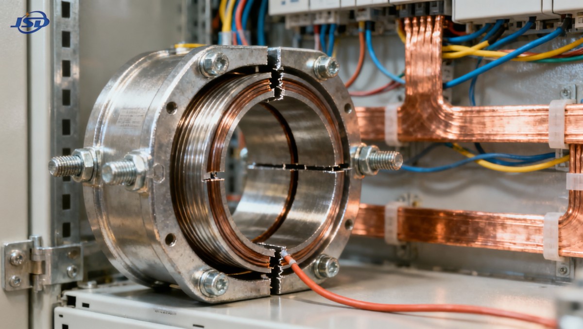
Unlike solid-core CTs, where the magnetic circuit is continuous and mechanically fixed during manufacturing, split-core devices depend entirely on mechanical closure to reconstruct that circuit. The core’s effective cross-sectional area, flux path length, and air gap distribution are all torque-sensitive. IEC 61869-2 and IEEE C57.13 specify accuracy classes (e.g., Class 0.5, Class 1.0) under defined mechanical and thermal conditions—but those standards assume proper mechanical assembly per manufacturer instructions. They do not define torque values; those are application-specific and must be derived from core material behavior and housing geometry.
Ferrite cores, common in lower-current (<100 A) monitoring units, are brittle and highly sensitive to compressive stress. Exceeding 0.8 N·m may cause measurable hysteresis shift and increased ratio error at low loads. Nanocrystalline cores, used in higher-accuracy (>0.2% class) or wide-bandwidth models, offer better saturation margin but exhibit pronounced permeability drop with even sub-millimeter air gaps—making torque control equally critical, though the acceptable window differs.
How to Identify Torque-Related Instability
Repeatability issues tied to torque rarely appear as gross failure. Instead, they manifest subtly:
- Measurements drift gradually over hours—not minutes—after initial installation, stabilizing only after thermal equilibrium;
- Identical CTs on parallel feeders show systematic offset (e.g., +0.7% on one, −0.4% on another), despite matching secondary wiring and meter settings;
- Phase angle error increases disproportionately at partial load (e.g., <30% of rated current), while ratio error remains within spec;
- Repeated “zero-load” checks yield inconsistent residual output (e.g., 12–28 mA instead of consistent <5 mA).
None of these point directly to torque—but collectively, they signal a compromised magnetic path. If electronic diagnostics (e.g., self-test routines, secondary burden verification) rule out wiring faults or meter-side errors, mechanical interface integrity becomes the logical next check.
Practical Torque Guidance—Without a Spec Sheet
Many split-core CTs ship without torque specifications, assuming installers rely on “snug fit” or visual alignment cues. That approach fails because human perception of “tight” varies widely—and finger-tightening typically delivers only 0.2–0.4 N·m, insufficient for most cores above 200 A rating.
A pragmatic, field-applicable method is the “three-turn rule”: Tighten the clamping screw until the core halves close fully, then apply an additional three full turns using a calibrated torque screwdriver set to 0.6–1.2 N·m, depending on core size and material. For larger units (e.g., 1000 A+), use a torque wrench with a 3–5 N·m range and follow the manufacturer’s stated value—if provided—or refer to published test data from independent labs like KEMA or CESI showing optimal torque vs. error curves for similar designs.
Crucially, torque must be applied evenly: alternate between opposing screws on multi-bolt housings, and verify core face contact by shining a bright LED flashlight along the seam—no visible light leakage should occur. If light passes through, re-torque incrementally until closure is complete.
When Core Integrity Isn’t Enough
Torque control addresses only one half of the measurement chain. Even perfectly torqued split-core CTs can deliver inconsistent readings if downstream components introduce noise, phase shift, or burden mismatch. High-impedance meters, long secondary runs (>3 m), or shared neutrals in multi-CT installations all contribute to uncertainty that masks or compounds torque-related effects.
For critical audit points—especially where harmonics, transients, or DC offset are present—the entire signal path must be validated. That includes verifying meter CT input impedance against CT secondary rating (e.g., 5 A CT into 0.1 Ω burden yields 0.25 V drop—well within most modern meter specs), checking grounding continuity, and confirming no shared return paths between CTs feeding different phases.
In demanding industrial applications—such as electrolysis plants or electroplating lines—where precise current measurement directly impacts process control and energy cost allocation, stability demands more than just a well-torqued CT. Here, isolation and rectifier transformers play a supporting but essential role: they provide galvanic separation, suppress common-mode noise, and ensure clean, stable voltage supply to rectifier-based loads. The Isolation and Rectifier Special Transformer is engineered for such environments, with copper windings, customizable low-voltage outputs, and compliance to IEC 60076—ensuring minimal interference upstream of current sensing points.
Verification Beyond Visual Inspection
Post-installation verification shouldn’t rely solely on meter display. Use a handheld clamp meter with known accuracy (±0.5% or better) to measure primary current simultaneously with the split-core CT’s output, converting via its stated ratio. Repeat this at least three load points (e.g., 20%, 50%, 100% of expected max). If deviation exceeds ±1% across points—or if repeatability between trials exceeds ±0.3%—recheck torque, core alignment, and secondary termination.
For long-term validation, log raw CT output (mV or mA) over 24–48 hours alongside a reference solid-core unit on the same conductor. Plot both datasets. Consistent offset suggests calibration or ratio error; drifting divergence points to thermal or mechanical instability—often torque-related.
No single parameter guarantees repeatability—but torque is the most controllable, most overlooked, and most immediately correctable factor in retrofit CT deployment. It bridges the gap between theoretical accuracy and field performance. Ignoring it turns a precision instrument into a variable resistor in the magnetic domain.

Get a Quote
Regardless of whether you require general advice or specific support, we are happy to help you.
Send Us Your Inquiry Today

Jinshida Electric remains committed to contributing to global energy development through professional manufacturing and superior service.