





Oil-Cooled Substation Transformers: Cooling Methods and Service Life
An oil cooled substation transformer stays within its thermal limits only when heat can move continuously from the windings and core into the insulating oil, through the tank or radiators, and finally into the surrounding air or water. A normal oil temperature does not by itself prove that the insulation system is healthy. The meaningful question is whether the temperature rise, load pattern, ambient condition, oil circulation, and cooling equipment behavior remain consistent with the transformer design.
Thermal stress is closely linked to insulation aging. Paper and pressboard insulation lose mechanical strength as exposure to elevated temperature continues. Oil also changes under heat, oxygen, moisture, and electrical stress. When cooling performance falls gradually, the transformer may continue carrying load without an immediate alarm, while the hottest parts of the winding experience a much higher temperature than the indicated top-oil temperature. This is why cooling assessment should combine readings, physical inspection, loading records, and oil test trends.
How the cooling circuit removes heat
Losses in the core and windings become heat. The oil adjacent to active parts warms, becomes less dense, and rises toward the upper tank. Cooler oil descends to replace it, creating natural circulation. Heat then passes through the tank wall or radiator panels into the ambient air. This simple circulation path is reliable when it remains clean, sealed, and properly matched to the load.
Cooling designations describe the medium and the circulation method. The first two letters refer to the internal insulating fluid and its movement; the second pair refers to the external cooling medium and its movement. The most common arrangements are summarized below.
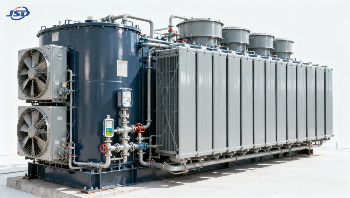
ONAN units are sometimes treated as maintenance-free because there are no pumps or fans. That assumption overlooks the importance of natural convection. A radiator that has been isolated by a closed valve, packed with debris, coated with a thick surface layer, or installed with inadequate free air space will reject less heat. Oil still circulates inside the tank, but the full cooling loop has been weakened.
Forced cooling introduces a different failure pattern. Fans can run while moving little useful air because louvers are blocked, blades rotate in the wrong direction after wiring work, or the radiator face is obstructed. Likewise, a pump motor may be energized while actual oil flow is inadequate due to a closed valve, air ingress, internal wear, or a blocked strainer. A running auxiliary device is not proof of cooling capacity.
Temperature readings need context
Top-oil temperature is useful for detecting general thermal loading, but it is not the winding hot-spot temperature. The difference between them changes with load current, oil circulation, cooling stage, winding geometry, and ambient conditions. A transformer operating at moderate top-oil temperature after a recent reduction in load may still have experienced excessive winding temperature before the oil had time to cool.
Compare temperatures against the same operating state whenever possible: similar load, similar cooling stage, and a comparable ambient temperature. A single value recorded on a hot afternoon has limited diagnostic value. A rising temperature trend at the same load is more informative, especially when no equivalent rise appears in ambient temperature.
Thermal imaging is valuable when used as a comparison tool rather than as a standalone acceptance test. Uneven radiator temperature can point to poor oil distribution, closed valves, fouling, or inactive fans. A warm connection may indicate elevated contact resistance rather than inadequate oil cooling. A hot tank area may reflect an internal magnetic flux path, circulating current, or localized loss. The image identifies an abnormal pattern; the load condition, phase comparison, and follow-up electrical checks determine its cause.
Oil condition and cooling performance are connected
Transformer oil has two simultaneous duties: it transfers heat and supports dielectric insulation. Moisture, oxidation products, sludge, and particles can reduce both functions. The effect is rarely limited to one parameter. Oxidation tends to increase acidity and generate polar compounds; these compounds can form deposits on paper, tank surfaces, and radiator passages. A deposit layer acts as thermal resistance, making heat transfer less effective even when oil level appears normal.
Water deserves particular attention because its location matters. Dissolved moisture in oil, moisture held in cellulose insulation, and free water are not equivalent conditions. As temperature changes, moisture moves between paper and oil. An oil sample collected after a load change may therefore show a different moisture condition from one taken during a stable operating period. Interpreting moisture results without load and temperature context can lead to unnecessary drying work or missed insulation risk.
Oil level is also easy to misread. Level changes naturally with oil temperature, so a level gauge must be read against the indicated temperature and the gauge markings. A persistently low level, a sudden deviation from prior seasonal behavior, or evidence of oil around seals calls for investigation. Air entering through a defective gasket or breather path accelerates oxidation and introduces moisture. Repeatedly adding oil without identifying the leakage or breathing problem only delays the underlying deterioration.
Sampling discipline prevents misleading results
Before taking an oil sample, verify the sampling point, container cleanliness, valve condition, and transformer operating state. The sample should represent the bulk oil rather than residue from a stagnant valve extension. Record the date, load, top-oil temperature, ambient temperature, cooling equipment status, oil level, and any unusual odor, sound, or visible leakage. Those details make future laboratory results comparable.
Dissolved gas analysis is often used to investigate internal electrical or thermal activity, but gas results should not be interpreted solely by whether a value crosses a generic threshold. The rate of change, gas relationships, transformer history, recent fault events, oil treatment, and sampling consistency all affect the conclusion. A sudden change after a known overload or switching event deserves a different response from a slow, stable pattern over a long interval. Laboratory interpretation should be integrated with temperature records and inspection findings.
Cooling faults that resemble each other
High top-oil temperature during peak load can arise from several distinct conditions. High ambient temperature raises the starting point for heat rejection. Excessive current creates additional winding loss. A fan-control fault reduces ONAF performance. Dirty radiators restrict air-side heat transfer. Low oil circulation can create a more serious internal thermal gradient. These conditions may produce a similar alarm, yet their corrective actions differ.
- Temperature rises with load, while radiators remain uniformly warm: the transformer may be approaching its available cooling capacity, particularly during high ambient conditions. Confirm actual load, tap position, cooling stage, and design rating before attributing the rise to a defect.
- One radiator bank is noticeably cooler than adjacent banks: inspect isolation valves, flow path, and physical blockage. A cool radiator is not always efficient; it may be receiving little hot oil.
- Fans operate but the top-oil temperature continues to climb: assess airflow direction, blade condition, fan cycling logic, radiator cleanliness, and whether all expected fan groups have started.
- Oil temperature rises without a corresponding load increase: examine ambient conditions, core-loss behavior, cooling controls, oil level, and the possibility of abnormal internal heating. Trend data becomes especially important here.
- Repeated high temperature after maintenance: review valve restoration, fan and pump wiring, thermostat settings, alarm contacts, and whether temporary covers or work materials were left near air inlets.
Sound can add useful evidence. A failed fan may be obvious, but changes in pump noise, irregular vibration, or intermittent relay operation should be recorded rather than dismissed. At the same time, increased transformer hum is not automatically a cooling issue. Core excitation, loose structural parts, or voltage conditions can change sound characteristics without causing an oil circulation fault.
Service-life decisions should focus on thermal history
Service life is governed mainly by the condition of the solid insulation, because oil can often be filtered, dried, reclaimed, or replaced while aged paper cannot be restored to its original strength. The practical aim is to avoid long periods of excessive hot-spot temperature, prevent moisture accumulation, and detect developing defects before they damage the cellulose system.
Short, controlled load peaks are different from persistent elevated temperature. Their effect depends on the initial oil temperature, cooling stage, duration, ambient condition, prior load, and transformer thermal capability. Treating every nameplate rating as a fixed operating limit without these conditions can be overly restrictive, while treating a short-term allowance as permission for repeated overload can accelerate aging. Records should distinguish routine loading from exceptional events.
Cooling upgrades are sometimes considered when load growth is expected. Adding or restoring forced-air cooling can be effective only if the transformer was designed for that stage and the corresponding controls, wiring, radiator capacity, and protection settings are correctly implemented. Installing extra fans beside a radiator does not automatically create a valid higher rating. The oil path, thermal design, current limits, and manufacturer documentation still govern the allowable duty.
For distribution applications using ONAN cooling, an oil-immersed unit such as the SBH15 Amorphous Alloy Transformer should be assessed as a complete thermal system: the amorphous alloy core affects no-load losses, while copper windings, radiator exposure, oil condition, and actual load profile determine the operating temperature response. Lower core loss can reduce background heat during lightly loaded operation, but it does not remove the need to investigate poor airflow, moisture, or abnormal winding loss.
Maintenance actions with the highest diagnostic value
Routine work should preserve a reliable baseline. Record top-oil and winding temperature indications, load, ambient temperature, oil level, cooler status, and alarm events at consistent operating intervals. Review changes rather than isolated values. A small but persistent shift often identifies a developing cooling problem earlier than a single high-temperature alarm.
Inspect radiator banks, fans, pumps, pipework, valve positions, cable glands, control cabinets, and visible seals. Look for oil staining, corrosion that affects heat-transfer surfaces, loose fan guards, blocked ventilation paths, abnormal vibration, and damaged louvers. Confirm that fan and pump automatic start signals work through their intended temperature stages, while maintaining the required safety isolation procedures.
Oil tests should follow a condition-based program suited to transformer criticality and operating history. Useful results may include moisture, dielectric strength, acidity, interfacial tension, dissolved gases, and particle or inhibitor condition where applicable. No single test replaces the others. For example, satisfactory dielectric strength does not rule out oxidation deposits, and an acceptable oil appearance does not confirm low moisture in the paper insulation.
After oil processing, radiator work, gasket replacement, or transport, allow the transformer condition to stabilize and verify the full cooling path before returning it to demanding duty. Air pockets, incorrect valve alignment, inadequate oil level, contaminated fittings, and untested automatic cooling controls are common sources of avoidable repeat work. A stable temperature trend under representative load is stronger evidence of successful restoration than a brief no-load observation.
Reliable oil cooling is ultimately measured by consistency: stable temperature behavior for the load and ambient condition, clean heat-transfer surfaces, intact oil containment, functioning auxiliary equipment, and test results that do not show deteriorating insulation conditions. When those signals diverge, treating the issue as a system problem rather than replacing a single visible component leads to a more defensible service decision.

Get a Quote
Regardless of whether you require general advice or specific support, we are happy to help you.
Send Us Your Inquiry Today

Jinshida Electric remains committed to contributing to global energy development through professional manufacturing and superior service.