





Oil-Cooled High-Voltage Transformers: Key Ratings for Grid Projects
Oil-Cooled High-Voltage Transformers: Key Ratings for Grid Projects
Selecting an oil cooled high voltage transformer for a grid project is not a matter of matching a primary voltage, secondary voltage, and MVA figure. Those values establish the starting point, but they do not show whether the transformer can withstand the network’s fault duty, operate within the site climate, maintain acceptable voltage regulation, or meet the owner’s expected service life.
For technical evaluators, the difficult part is usually not reading a nameplate. It is identifying where nameplate ratings interact with the real system: fluctuating renewable generation, high ambient temperatures, constrained substation space, changing load profiles, parallel transformer operation, and utility protection requirements. A transformer that appears suitable in a tender comparison can become a long-term operating concern if these interactions are not resolved during design review.
The most useful approach is to treat the transformer as part of a complete electrical and thermal system. Its rated values must be checked against the grid study, installation conditions, applicable standards, protection philosophy, and maintenance capability—not assessed in isolation.
Start With the Duty, Not the Nominal Voltage
An oil cooled high voltage transformer may serve a transmission substation, a large industrial intake, a renewable-energy collection point, a railway supply system, or critical infrastructure. These duties can have very different electrical characteristics even when the nominal voltage ratio is similar.
A project specification should therefore define the expected operating envelope: continuous load, seasonal load variation, emergency loading assumptions, harmonic content where relevant, voltage range at the high-voltage terminals, fault level, altitude, ambient temperature, seismic exposure if applicable, and restrictions on outage windows. A transformer designed for a steady base-load substation may need a different thermal or tap-changing approach from one installed beside a wind or solar plant with frequent voltage movement.
The rated power should be understood in this context. MVA capacity is limited by temperature rise and insulation performance under defined conditions. It is not simply a promise that the unit can carry any load up to that number indefinitely, regardless of cooling availability or ambient temperature. If a project expects overload operation, the evaluator should ask how that duty is defined, what cooling stages are available, and whether the proposed loading assumptions align with the governing standard and the asset owner’s rules.
Ratings That Need to Be Read Together
The core ratings of a power transformer are connected. Reviewing them one by one is necessary, but reviewing their combined effect is where sound technical evaluation begins.
Rated voltage, vector group, and tap changer
Rated voltage needs to be checked against the system’s highest voltage for equipment, not just its commonly quoted nominal voltage. This distinction affects insulation coordination, bushing selection, clearances, and test requirements. The winding connection and vector group also deserve careful attention. They influence phase displacement, grounding arrangements, zero-sequence behavior, harmonic paths, and whether the unit can operate in parallel with existing transformers.
Tap range is often treated as a routine schedule item, yet it can determine whether a substation maintains the required downstream voltage during heavy load or renewable generation swings. Evaluators should distinguish between off-circuit taps, intended for de-energized adjustment, and on-load tap changers designed to regulate while energized. For OLTC applications, the regulation duty, control scheme, tap position monitoring, diverter-switch maintenance strategy, and available short-circuit capacity should be reviewed alongside the transformer itself.
Impedance is a system setting
Percentage impedance controls more than voltage drop. It materially affects prospective short-circuit current on the lower-voltage network and determines how transformers share load when operated in parallel. A lower impedance can support stronger voltage regulation but may raise fault duty beyond the capability of switchgear or cables. A higher impedance can reduce fault current, but it may increase voltage variation under load.
The correct value is therefore project-specific. It should be derived from a coordinated network study rather than copied from an earlier procurement package. If multiple units are planned for parallel operation, impedance tolerances, voltage ratio, vector group, tap positions, and MVA ratings all need to be considered together. A technically compliant transformer can still create operational imbalance when these parameters are not aligned.
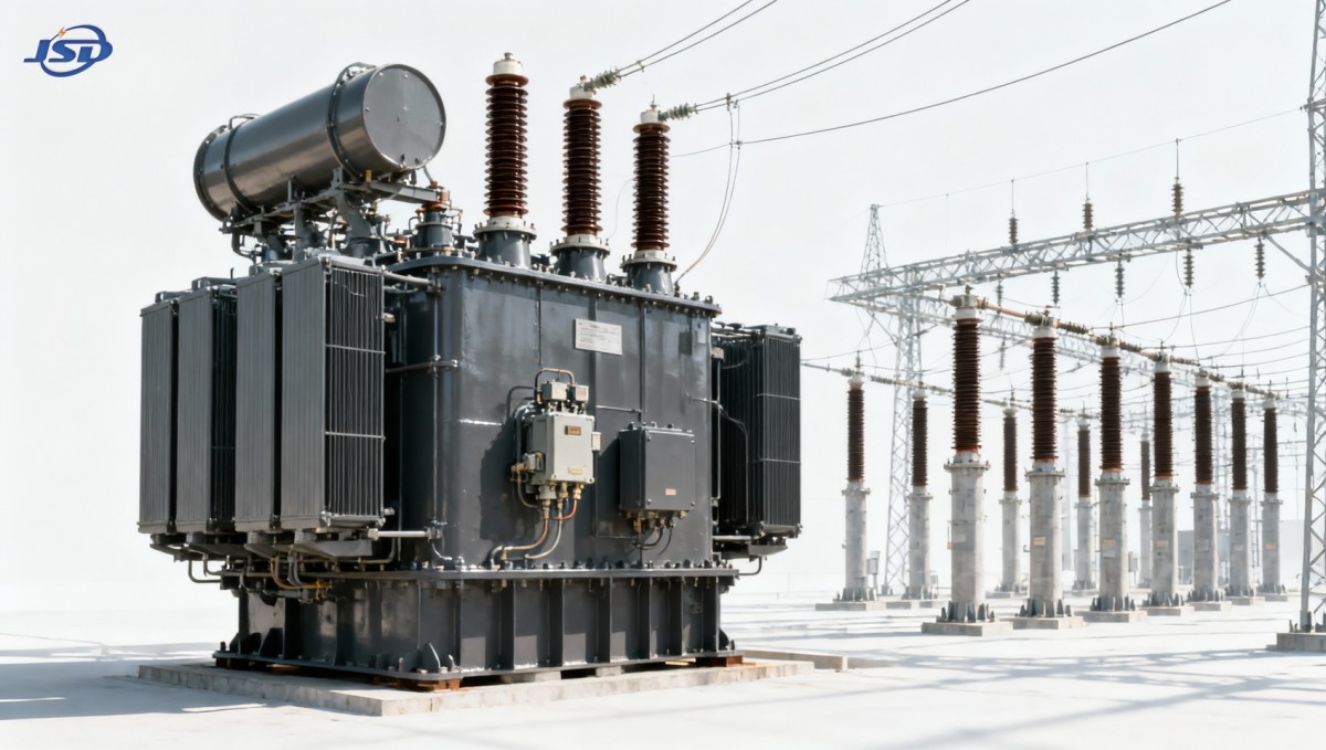
Insulation Levels: Looking Beyond Routine Operation
A grid transformer spends most of its life at normal system voltage, but insulation design is judged by its ability to survive non-routine electrical stress. Lightning impulses, switching impulses on higher-voltage systems, temporary overvoltages, and internal fault-related stresses must be considered through the project’s insulation-coordination study.
For an oil-immersed unit, the insulation system includes more than liquid dielectric strength. It includes winding insulation, pressboard and other solid insulation, lead arrangement, bushings, clearances, and the management of electric-field stress. The requested lightning impulse withstand level and, where applicable, switching impulse withstand level should be consistent with the network voltage class, arrester protective levels, line configuration, and utility practice.
It is also worth checking test documentation requirements early. IEC 60076 is widely used as a reference framework for power transformers, but project specifications can add utility-specific requirements for routine, type, special, or witness tests. The applicable edition, scope, and acceptance criteria should be unambiguous in the technical schedule. Broad references to “IEC compliant” are rarely enough for a complex grid procurement.
Cooling Class, Temperature Rise, and the Reality of Site Conditions
Oil cooling transfers heat from the windings and core through insulating liquid and radiators or coolers to the surrounding air or water. The cooling designation identifies the method of circulation and heat removal, such as natural oil and air circulation or forced stages using pumps and fans. The designation itself is useful, but evaluators need the complete thermal picture: rated output by cooling stage, guaranteed temperature-rise limits, control logic, auxiliary supply reliability, and behavior after a fan or pump failure.
Ambient temperature and altitude can materially change the available cooling margin. Restricted airflow around radiators, solar exposure, dust accumulation, or a poorly ventilated transformer bay can further reduce heat dissipation. Where water cooling is proposed, water quality, leakage detection, and maintainability become part of the reliability assessment. A technically attractive cooling arrangement is not necessarily the most resilient one if site maintenance resources are limited.
Oil temperature indicators, winding temperature indicators, pressure-relief devices, oil-level monitoring, cooling control panels, and gas detection arrangements should be considered as a coordinated protection and monitoring package. Their exact configuration depends on transformer size, owner practice, and site criticality. The important question is whether alarms and trips are meaningful, accessible, and integrated into the substation’s operating procedures.
Losses Are an Operating Cost, Not a Catalogue Detail
No-load loss is associated mainly with core magnetization and is present whenever the transformer is energized. Load loss rises with current and includes winding-related losses as well as additional stray losses. Their relative importance changes with the annual loading profile. A lightly loaded unit may make no-load loss particularly significant, while a heavily loaded transformer can be more sensitive to load loss and cooling energy consumption.
For this reason, loss comparison should use the purchaser’s stated capitalization method or life-cycle-cost model where one is specified. Comparing only the lowest initial price can conceal a meaningful difference in long-term energy cost. Technical review should also confirm the reference temperature for load losses and whether auxiliary losses from fans, pumps, and controls are addressed in the evaluation method.
Sound level deserves similar attention in urban, industrial, and infrastructure sites. Core excitation, winding forces, cooling fans, and pumps all contribute. If there is a boundary noise requirement, it should not be assumed that a transformer sound-power guarantee alone resolves the issue. Distance, enclosure design, reflections, surrounding structures, and operating cooling stages may all need to be considered.
Short-Circuit Withstand Must Be More Than a Declaration
Short circuits impose extreme electromagnetic and thermal forces on transformer windings. The transformer’s ability to withstand them depends on the available fault current, fault clearing time, winding geometry, conductor support, clamping system, and mechanical integrity of the active part. A short-circuit withstand statement should be evaluated against the actual system study, including credible future network conditions where those are defined by the owner.
This subject becomes especially important where source capacity is increasing, distributed generation is added, or a substation is being expanded in phases. The fault level at commissioning may not be the highest fault level the transformer experiences during its service life. Technical clarifications should identify the required current magnitude and duration, rather than relying on a generic confirmation of compliance.
Oil System, Accessories, and Maintainability
Oil is both a coolant and a critical part of the insulation system. The design review should cover the selected insulating liquid, sealing approach, conservator arrangement where used, breather system, oil sampling access, filtration provisions, and containment requirements. Fire safety and environmental controls are strongly influenced by local codes and site layout, so bunding, separation distances, fire barriers, drainage, and detection interfaces need early coordination with civil and fire-protection teams.
Accessories can also determine whether maintenance is straightforward or disruptive. Bushing current transformers, marshalling cabinets, terminal arrangements, radiator isolation valves, lifting and jacking points, transport dimensions, and spare-part philosophy should be checked before manufacturing drawings are released. The required degree of online monitoring should reflect asset criticality. More sensors are not automatically better if the project has no practical plan for interpreting alarms or acting on the resulting data.
Oil-filled power transformers are not the answer to every location. In buildings, hospitals, data centers, underground structures, or sites with stringent fire-risk constraints, a dry-type distribution solution may be more appropriate. For example, the SCB10-12 10kV Cast Resin Dry-Type Distribution Transformer is designed for 10 kV to 0.4 kV distribution duties, with capacities from 30 to 2500 kVA and options that can be matched to industrial and commercial installations. This is not a direct substitute for a high-voltage grid transformer; it illustrates why cooling medium, fire performance, voltage class, and installation environment should be assessed as one decision.
Turning a Specification Into a Reliable Procurement Decision
A robust technical specification should clearly separate fixed network requirements from supplier design responsibilities. It should state voltage and insulation levels, MVA ratings by cooling stage, vector group, impedance requirements and tolerances, tap-changer duty, loss evaluation basis, sound limits, climatic conditions, fault withstand duty, required tests, documentation, and site constraints. Ambiguity in these items often reappears later as design exceptions, commercial variation, or commissioning delays.
Factory acceptance testing is an important control point, but it cannot compensate for an incomplete specification. Evaluators should define the tests they need to witness, the reports required before shipment, and the handling of deviations. Transport and installation planning matter as well: total mass, oil transport strategy, site assembly, vacuum treatment requirements, commissioning tests, and energization support should be consistent with the project schedule.
Jinshida Electric Power Technology Co., Ltd. approaches power equipment development through engineering review, controlled manufacturing processes, and quality management focused on stable operation in grid, industrial, renewable-energy, and infrastructure applications. For a project team, the practical value of that approach is a clearer conversation about ratings, tolerances, test obligations, and maintainability before the unit reaches site.
The best transformer selection is rarely the one with the most impressive isolated figure. It is the unit whose electrical ratings, thermal capability, insulation coordination, protection interfaces, and service conditions have been checked against the actual network. Before finalizing a purchase decision, confirm the latest load flow and short-circuit studies, site ambient conditions, governing standard clauses, parallel-operation requirements, and the owner’s maintenance expectations. Those checks are usually more valuable than another round of nameplate comparisons.

Get a Quote
Regardless of whether you require general advice or specific support, we are happy to help you.
Send Us Your Inquiry Today

Jinshida Electric remains committed to contributing to global energy development through professional manufacturing and superior service.